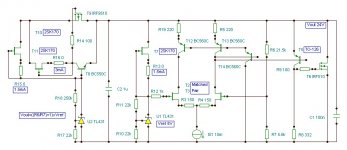
aparatusonitus said:your R12 should be parallel resistance of R2 + R6.
Wouldn't that result in an inapproriate high R12 or low R2/R6 string that would eat all current? It would need to be as low as 6R and 16,5R?
Rüdiger
I think you mean the input resistor to Q4. The impedance is already matched.
What is the advantage of your Central CS, it has comparativly huge parts count, where other people seem to get by with LM317 wired as CS?
Rüdiger
What is the advantage of your Central CS, it has comparativly huge parts count, where other people seem to get by with LM317 wired as CS?
Rüdiger
Next time I'll do the math with my fingers instead using my head, you are right, your error amplifier input impedances are good.
Why use discrete master current source instead LM317? Becouse constant-current characteristic of LM317 tends to become deteriorated in the high frequency range much more against discrete CCS, but you could use one LM317 as floating preregulator Walt Young superegulator style as it will clean some garbage from mains.
Why use discrete master current source instead LM317? Becouse constant-current characteristic of LM317 tends to become deteriorated in the high frequency range much more against discrete CCS, but you could use one LM317 as floating preregulator Walt Young superegulator style as it will clean some garbage from mains.
Hi,aparatusonitus said:.........Why use discrete master current source instead LM317? Becouse constant-current characteristic of LM317 tends to become deteriorated in the high frequency range much more against discrete CCS,.........
the fast shunt regulator hides the slowness of the 317 current source.
I think the 317's only disadvantage in the fast shunt context is high voltage drop. That's why I asked for low voltage drop alternatives and why I was so interested in the voltage drop that On's CCS achieves.
Hi,
in sim, using zenys CSS gives an 30dB improvment of high frequency ripple rejection above 100kHz (the graph is acutally more complicated).
With aparatus' CSS I had no improvement, but, since no part values are given, I could have chosen wrong values.
One has to adjust R12 to get the same current, though.
Rüdiger
Uh-oh.
Things are more complicated. The sims tells a tendency of oscillation. And you screw up the high F's regulation with that LED at the output of the CS.
Don't know what's going on.
Rüdiger
EDIT: it's mostly wrong what I#ve written regarding those different CSS. The sim results are supersided by the ESR your provide for the caps...
I checked the real circuit again at the workbench. It seems, if I use no current source, or current mirror for the diff-pair (j4 in the schematic) I got lower noise. With an active mirror or -source, I can see some noise on the scope at the output of the reg (5mV/div).
And what are your concerns against LEDs? There was a hot debate some years ago here about the noise of leds which led to no consensus (well, not that I know a single issue or thread where consensus had been found...)
Rüdiger
And what are your concerns against LEDs? There was a hot debate some years ago here about the noise of leds which led to no consensus (well, not that I know a single issue or thread where consensus had been found...)
Rüdiger
Onvinyl said:With aparatus' CSS I had no improvement, but, since no part values are given, I could have chosen wrong values.
I don't know your load current request, but if you going to try Masao Noro CCS, start with something like 10R for current defining resistor and 681R for the other. For Qs use something like 2SA872/2SA970 and MJE1503x/D4xH11.
Noro's patent has all values for parts .
good for analysis
patent 4366432
useful link:
http://www.pat2pdf.org/
good for analysis
patent 4366432
useful link:
http://www.pat2pdf.org/
Thanks Zen Mod, that gives me a few ideas. I don't see, though, were my main CSS has major flaws. I'll try fet/resistor reference in order to achieve lower noise.
By the way, the use of the cfp in the diff-amp lowers Zout by a factor of 20.
@Andrew: with 100mA, the real reg could have a voltage drop of only 1 Volt. I don't think it's optimum in regard of regulation, though
Rüdiger
By the way, the use of the cfp in the diff-amp lowers Zout by a factor of 20.
@Andrew: with 100mA, the real reg could have a voltage drop of only 1 Volt. I don't think it's optimum in regard of regulation, though
Rüdiger
the lowest input voltage (Vimin) - Vdrop = max Vout.Onvinyl said:@Andrew: with 100mA, the real reg could have a voltage drop of only 1 Volt.
If Vdrop goes up then a higher voltage transformer is required.
Go down that route and all the dissipations go even higher when mains voltage is running at maximum.
There is a big advantage in component size and heatsink requirement and internal heat generation by adopting the lowest Vdrop for the CCS. It should not affect the operation of the shunt or the circuit. It's simply down to heat.
Hi Andrew,
If you have 100mA, R12 alone eats 0.47 volts. If you have 400mA, then it drops 1.8 volts and so on.
Rüdiger
If you have 100mA, R12 alone eats 0.47 volts. If you have 400mA, then it drops 1.8 volts and so on.
Rüdiger
NO!.Onvinyl said:R12 alone eats 0.47 volts. If you have 400mA, then it drops 1.8 volts and so on.
R12 is part of the CCS.
The voltage across R12 is set by the Vbe of the CCS transistor. A slight correction for the 10k on the base lead means that R12 always has near 600 to 650mV irrespective of the chosen CCS current.
AndrewT said:NO!.
R12 is part of the CCS.
The voltage across R12 is set by the Vbe of the CCS transistor.
...as long as it's working... Andrew, I have to check what's wrong there. Will take some days, though.
Rüdiger
I couldn't wait. Well, both CS-Q's are easily destroyed. It wasn't obious, because the voltage drop across R12 when using it alone happens to be 0.6 Volts in my setup...
Fixed it. The CS-voltage drop is 0.7 volts. The reg as a whole is best used at 2 Vdrop minimum.
Rüdiger
Fixed it. The CS-voltage drop is 0.7 volts. The reg as a whole is best used at 2 Vdrop minimum.
Rüdiger
Hi Rudiger,
how are things going? Round and round? However, you are going for a nice project this time. Shunt regulators are popular in Germany, right? Well, they offer excellent sonic performance due to low deteriorating level, Class A operation, not much harmful global negative feedback generated effects here...
The active series pass element (instead of resistor), improves ripple rejection, further improvements are possible by using more adequate current sources and voltage references. Even the LTP would deserve and highly appreciate a better CCS for its function. 1KOhm is a very low impedance compared to the achievable several tens of MOhms. Light diodes are noisy having a zener-like behavior.
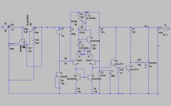
May I come up with a slightly different version?
Both series and parallel regulators need a lot of internal feedback. FETs are much more accurate for voltage to current conversion than bipolars.
The LTP is heavily simplified.
how are things going? Round and round? However, you are going for a nice project this time. Shunt regulators are popular in Germany, right? Well, they offer excellent sonic performance due to low deteriorating level, Class A operation, not much harmful global negative feedback generated effects here...
The active series pass element (instead of resistor), improves ripple rejection, further improvements are possible by using more adequate current sources and voltage references. Even the LTP would deserve and highly appreciate a better CCS for its function. 1KOhm is a very low impedance compared to the achievable several tens of MOhms. Light diodes are noisy having a zener-like behavior.
May I come up with a slightly different version?
Both series and parallel regulators need a lot of internal feedback. FETs are much more accurate for voltage to current conversion than bipolars.
The LTP is heavily simplified.
Attachments
Hi Lumba,
thanks for this *very* useful contribution!
Your T14, however, does not turn in my simulation, still keeping my upside-down error amp configuration. As I understand it, it should be part of the current mirror (T12, T13) but probably I'm wrong.
Your input CSS looks tricky, I'll chew on this a bit...
thanks,
Rüdiger
Hm, I tried a more simpler configuration, think my initial post but with 2-bjt current mirror. Whatever I do, I could not make the error amplifier turn on with a current source at the tail. This is hold true with both my perfboard in reality and the simulation.
Rüdiger
Rüdiger
Onvinyl said:Your T14, however, does not turn in my simulation, still keeping my upside-down error amp configuration. As I understand it, it should be part of the current mirror (T12, T13) but probably I'm wrong.
T14 is part of CM (only "funny" drown), it should only supplay current for the bases of T12/13.
Leaving T14 for now.
I have the problem, that with a current source in the diffpair tail, the error amp does (often) not work, if the output compound pair (Q1, M1) is attached. With resistor in the tail, this is no problem. I first had this problem with the real circuit, but the sim shows the same behaviour with a non-ideal current source.
So I inserted Q8, an E-follower which also helps Zout in the high freq region a lot.
But, since I did not check if it works in reality, and there might stability issues as well, *and* it was an attempt out of pure desparation: why doesn't it work without Q8?
Rüdiger
Attachments
- Status
- Not open for further replies.
- Home
- Amplifiers
- Solid State
- Simple shunt reg