I did a search and did a lot of reading but cannot find the answer to some specific questions.
What components of the Simple SE circuit determine the grid voltage?
I am playing with SE Amp CAD and I understand the effect of of the cathode bias resistor (Rk) on the current (mA) but how do I know what value to enter for grid voltage (Vin)?
I have been using values from George's simulation tables, but I want to understand how those values were/are determined?
Is it a value that can be changed independantly/manually, or is it a result of a combination of B+, cathode resistance, etc.? Is it something I can calculate based on the other three values?
Sorry if this is another annoying amateur question.
I see now that George refers to "Vin" as "Vin is the AC drive level in peak AC volts."
I have no idea what that means, or how that value is determined.
I have no idea what that means, or how that value is determined.
I have been able to determine that Vin does not equal grid voltage. When I change Vin, idle grid voltage remains the same, however I can see that when I change Vin the Vg max and Vg min change...
Slowly starting to get it. So Vin ("the AC drive level in peak AC volts") is the peak AC voltage coming from the 12AT7? How do I know what that value is?
George used a value of 38 for Vin. Am I to assume that's the correct (and static) value I should use to sim the SSE?
Slowly starting to get it. So Vin ("the AC drive level in peak AC volts") is the peak AC voltage coming from the 12AT7? How do I know what that value is?
George used a value of 38 for Vin. Am I to assume that's the correct (and static) value I should use to sim the SSE?
Last edited:
... So Vin ("the AC drive level in peak AC volts") is the peak AC voltage coming from the 12AT7? How do I know what that value is?...
Yes. You can measure it, if you like ...
When I did it, I jumpered the current limiting resistor, and looked at the maximum p-p output I could get from the 12AT7 before it broke up. Some measurements I took with an AC VTVM, which are probably sort of accurate, assuming I did it right, and am reading my notes accurately ...
12AT7 grid ac p-p 12AT7 plate VDC max ac p-p output
1.8 250 70
3.8 300 140
4.0 350 190
I think I used the HI Z load on my meter, since the 12AT7 is driving 220K on the SSE ...
It looks like from my notes that at the typical 250 - 300 vdc on the 12AT7 plate, 1 KHz @ 1 v p-p at the 12AT7 grid input gets about 40 p-p at the plate output. So 38 to 40 looks like a good number for Vin, but it can do a lot more than that with enough drive.
There is a companion to SE Amp Cad called Tube Cad, I think, but I haven't used it much.
Hope this helps.
I did a search and did a lot of reading but cannot find the answer to some specific questions.
What components of the Simple SE circuit determine the grid voltage?
I am playing with SE Amp CAD and I understand the effect of of the cathode bias resistor (Rk) on the current (mA) but how do I know what value to enter for grid voltage (Vin)?
I have been using values from George's simulation tables, but I want to understand how those values were/are determined?
Is it a value that can be changed independantly/manually, or is it a result of a combination of B+, cathode resistance, etc.? Is it something I can calculate based on the other three values?
Sorry if this is another annoying amateur question.
You don't say it but I assume you are interested in the DC conditions.
The grid voltage in itself is not of particular interest, what is important for the circuit is the Vgk, the voltage between grid and cathode as that determines the tube 'positioning'.
Since the grid is at gnd for DC, and the K is at (Ia*Rk), the grid voltage is simply the negative of the cathode voltage.
You get the negative grid voltage (referred to C!) by raising C with Rk and leaving G at DC gnd.
Jan
...
What components of the Simple SE circuit determine the grid voltage?
...
At the 12AT7 grid, the ac voltage is determined by the level of ac drive. The dc bias voltage is determined by the voltage developed across the cathode resistor, just change the sign. edit: this will usually be - 1.7 to -1.8 vdc ish.
At the power tube grid, the ac voltage is the amplified input voltage from the 12AT7. The dc bias voltage is determined by the voltage developed across the cathode resistor, just change the sign.
Some one can correct me if I'm wrong.
Last edited:
Yes. You can measure it, if you like ...
When I did it, I jumpered the current limiting resistor, and looked at the maximum p-p output I could get from the 12AT7 before it broke up. Some measurements I took with an AC VTVM, which are probably sort of accurate, assuming I did it right, and am reading my notes accurately ...
12AT7 grid ac p-p 12AT7 plate VDC max ac p-p output
1.8 250 70
3.8 300 140
4.0 350 190
I think I used the HI Z load on my meter, since the 12AT7 is driving 220K on the SSE ...
It looks like from my notes that at the typical 250 - 300 vdc on the 12AT7 plate, 1 KHz @ 1 v p-p at the 12AT7 grid input gets about 40 p-p at the plate output. So 38 to 40 looks like a good number for Vin, but it can do a lot more than that with enough drive.
There is a companion to SE Amp Cad called Tube Cad, I think, but I haven't used it much.
Hope this helps.
Thanks very much for that. I understand most of it, I think. 🙂
When you say "it (the 12AT7) can do a lot more than that with enough drive" do you mean drive on the amp inputs (like from a pre-amp) ?
I think (hope) I am starting to understand "drive".
Last edited:
At the 12AT7 grid, the ac voltage is determined by the level of ac drive. The dc bias voltage is determined by the voltage developed across the cathode resistor, just change the sign. edit: this will usually be - 1.7 to -1.8 vdc ish.
At the power tube grid, the ac voltage is the amplified input voltage from the 12AT7. The dc bias voltage is determined by the voltage developed across the cathode resistor, just change the sign.
Some one can correct me if I'm wrong.
Hopefully this is correct, because it is starting to make much more sense to me now. Thanks again.
You don't say it but I assume you are interested in the DC conditions.
The grid voltage in itself is not of particular interest, what is important for the circuit is the Vgk, the voltage between grid and cathode as that determines the tube 'positioning'.
Since the grid is at gnd for DC, and the K is at (Ia*Rk), the grid voltage is simply the negative of the cathode voltage.
You get the negative grid voltage (referred to C!) by raising C with Rk and leaving G at DC gnd.
Jan
Sorry, not ignoring you Jan. While I trust that this is all technically accurate (I have gained respect for your knowledge in hundreds of posts over the years) I have to admit it is beyond my current comprehension.
Thanks for your effort and patience.
I do think I have the answer I needed to continue playing with SE Amp CAD. 🙂
Note: The title of the thread is actually wrong, because up until a few hours ago I thought grid voltage and "Vin" were the same thing.
I now understand they are not, and it is the "Vin" value that I was trying to understand - and I think I do now.
Thanks and sorry for the confusion.
I now understand they are not, and it is the "Vin" value that I was trying to understand - and I think I do now.
Thanks and sorry for the confusion.
Technically speaking the output tube in an amplifier has both an AC voltage (the test sine wave, or the music signal) and a DC voltage applied to it. Both are required to control the flow of current through the tube.
These voltages are applied between the grid pin and the cathode pin of the tube. For most tubes the grid must have a negative voltage on it with respect to the cathode. The magnitude of this negative voltage will control how much current flows through the tube. A DC voltage of over -80 volts on the grid will cause all current to cease flowing through the tube. A voltage of near zero will cause maximum current flow through the tube. In an amp we adjust this idle voltage to get the desired idle current flow through the tube.
This DC voltage can be obtained two ways. The cathode can be connected to circuit ground, and a negative voltage can be applied to the grid of the tube, through a resistor, vacuum tube, mosfet, or transformer winding. The Tubelab TSE and TSE-II use this method.
The grid can be connected to ground through a resistor, or other path, and a positive voltage can be applied to the cathode, usually through a resistor in parallel with a bypass capacitor. The Tubelab SSE uses this method.
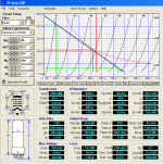
The DC grid voltage shown in your SE Amp Cad simulation shows a typical SSE type design with a 680 ohm cathode resistor. This puts 42.3 volts on the cathode and zero DC volts on the grid, resulting in an idle current of 63.2 mA and about 26 watts of tube dissipation at idle. Under IDEAL conditions with an IDEAL vacuum tube these conditions should not change from zero volume to the point of clipping.
Up to this point there is no signal applied to the amp, or the volume is turned all the way down.....and we are listening to nothing.
We can apply signal to this amp. This is an AC voltage that is fed to the grid along with the DC voltage. This is called Vin by SE Amp Cad.
If we applied a sine wave and just cracked the volume pot we might be putting 2 volts Peak to Peak into the grid of our tube. This will cause the grid of the tube to move up one volt to -41.3 volts on the positive peak of the sine wave, and move down one volt to -43.3 volts on the negative peak of the sine wave. This movement increases as we turn up the volume.
The 12AT7 as it is set up in the SSE will have a gain of about 45 to 50. This is enough gain to ram 50 volts into the EL34 when driven from a typical consumer device without requiring a preamp. It also has enough head room to deliver over 100 volts to that poor output tube when overdriven. This is done to minimize distortion in the 12AT7, since it is not operated anywhere it's maximum capabilities. So, how much signal does our amp need.
This is where the 38 volts comes from.
Your sim shows that when 40 volts is applied to the EL34 under the conditions chosen, you will get 13.1 watts of power (neglecting OPT losses) and be creating 8.3% of second harmonic distortion, and 0.3% of third harmonic distortion. If you were to run the same sim at less Vin you would see less power output, and less distortion.
I typically run several dozen sims at various combinations of DC voltages, cathode resistors, and load impedances to find out what works best for a given tube. To get an apples to apples comparison, you keep ALL of the conditions the same from sim to sim except for what you are looking at. For example I could try a different cathode resistor, but keep all other things the same.
I always start at a low Vin and keep increasing it until I reach a distortion threshold that I do not want to exceed. The sims I did during the development of the SSE probably used a figure of 5% total 2H and 3H. My guess is that you will probably get pretty close to 5% if you back your 40 volts down to 38.
15 years have passed since I did those sims. SE amp cad was a good tool in the day, but it relies on good vacuum tube curves like any simulator, and like most sims, gives optimistic distortion and power output numbers. Today, I use LT Spice, and set my max THD threshold at 3%. LT spice allows for simulation of the entire amp at once, not just a single triode only stage. It is also far more involved to use.
Linear Technology actually came into the plant where I worked many years ago to demonstrate LT spice. Myself and their tech guy spent a couple hours simulating the SSE amp design. I probably still have that sim on a hard drive somewhere. I think it used a 6L6GC since that was the only model that we could find.
If you were to start at 1 volt and run 40 sims at one volt intervals and plot the results, you would see a typical distortion curve with pretty low numbers up to a point where it takes off and climbs near vertically. This is the point where more drive into the amp gives no more power output, only more distortion, often called clipping.
Once we find the Vin needed to push the output tube into clipping, we have the data needed to figure out how much gain is needed in the driver (12AT7) stage. That's where TubeCad was used 15 years ago. A typical iPOD or cell phone puts out about 0.75 to 1 V peak. A gain of 45 to 50 is needed to turn this into 38 volts of drive. A good CD player puts out more than this, so a volume pot is usually all that's needed between the CD player and the SSE.
These voltages are applied between the grid pin and the cathode pin of the tube. For most tubes the grid must have a negative voltage on it with respect to the cathode. The magnitude of this negative voltage will control how much current flows through the tube. A DC voltage of over -80 volts on the grid will cause all current to cease flowing through the tube. A voltage of near zero will cause maximum current flow through the tube. In an amp we adjust this idle voltage to get the desired idle current flow through the tube.
This DC voltage can be obtained two ways. The cathode can be connected to circuit ground, and a negative voltage can be applied to the grid of the tube, through a resistor, vacuum tube, mosfet, or transformer winding. The Tubelab TSE and TSE-II use this method.
The grid can be connected to ground through a resistor, or other path, and a positive voltage can be applied to the cathode, usually through a resistor in parallel with a bypass capacitor. The Tubelab SSE uses this method.
The DC grid voltage shown in your SE Amp Cad simulation shows a typical SSE type design with a 680 ohm cathode resistor. This puts 42.3 volts on the cathode and zero DC volts on the grid, resulting in an idle current of 63.2 mA and about 26 watts of tube dissipation at idle. Under IDEAL conditions with an IDEAL vacuum tube these conditions should not change from zero volume to the point of clipping.
Up to this point there is no signal applied to the amp, or the volume is turned all the way down.....and we are listening to nothing.
We can apply signal to this amp. This is an AC voltage that is fed to the grid along with the DC voltage. This is called Vin by SE Amp Cad.
If we applied a sine wave and just cracked the volume pot we might be putting 2 volts Peak to Peak into the grid of our tube. This will cause the grid of the tube to move up one volt to -41.3 volts on the positive peak of the sine wave, and move down one volt to -43.3 volts on the negative peak of the sine wave. This movement increases as we turn up the volume.
So Vin ("the AC drive level in peak AC volts") is the peak AC voltage coming from the 12AT7? How do I know what that value is? George used a value of 38 for Vin. Am I to assume that's the correct....."it (the 12AT7) can do a lot more than that with enough drive" do you mean drive on the amp inputs
The 12AT7 as it is set up in the SSE will have a gain of about 45 to 50. This is enough gain to ram 50 volts into the EL34 when driven from a typical consumer device without requiring a preamp. It also has enough head room to deliver over 100 volts to that poor output tube when overdriven. This is done to minimize distortion in the 12AT7, since it is not operated anywhere it's maximum capabilities. So, how much signal does our amp need.
This is where the 38 volts comes from.
Your sim shows that when 40 volts is applied to the EL34 under the conditions chosen, you will get 13.1 watts of power (neglecting OPT losses) and be creating 8.3% of second harmonic distortion, and 0.3% of third harmonic distortion. If you were to run the same sim at less Vin you would see less power output, and less distortion.
I typically run several dozen sims at various combinations of DC voltages, cathode resistors, and load impedances to find out what works best for a given tube. To get an apples to apples comparison, you keep ALL of the conditions the same from sim to sim except for what you are looking at. For example I could try a different cathode resistor, but keep all other things the same.
I always start at a low Vin and keep increasing it until I reach a distortion threshold that I do not want to exceed. The sims I did during the development of the SSE probably used a figure of 5% total 2H and 3H. My guess is that you will probably get pretty close to 5% if you back your 40 volts down to 38.
15 years have passed since I did those sims. SE amp cad was a good tool in the day, but it relies on good vacuum tube curves like any simulator, and like most sims, gives optimistic distortion and power output numbers. Today, I use LT Spice, and set my max THD threshold at 3%. LT spice allows for simulation of the entire amp at once, not just a single triode only stage. It is also far more involved to use.
Linear Technology actually came into the plant where I worked many years ago to demonstrate LT spice. Myself and their tech guy spent a couple hours simulating the SSE amp design. I probably still have that sim on a hard drive somewhere. I think it used a 6L6GC since that was the only model that we could find.
If you were to start at 1 volt and run 40 sims at one volt intervals and plot the results, you would see a typical distortion curve with pretty low numbers up to a point where it takes off and climbs near vertically. This is the point where more drive into the amp gives no more power output, only more distortion, often called clipping.
Once we find the Vin needed to push the output tube into clipping, we have the data needed to figure out how much gain is needed in the driver (12AT7) stage. That's where TubeCad was used 15 years ago. A typical iPOD or cell phone puts out about 0.75 to 1 V peak. A gain of 45 to 50 is needed to turn this into 38 volts of drive. A good CD player puts out more than this, so a volume pot is usually all that's needed between the CD player and the SSE.
George,
I know your time is spread thin so I really appreciate the time you have taken to explain this. It is nearly crystal clear to me at this point. The best part about building this amp is the fact that it is inspiring me to learn stuff that I have been curious about for quite some time. Now that you have explained the "big picture" I feel like there is some context for all the bits and pieces.
Working on projects like this keeps me sane, so again thank you for everything; designing the board, all the info and instructions on your site, and the after sales support and education. Amazing, really. I wish I could buy you a beer or two.
By the way, my amp will have the volume pot omitted and will be fed by a solid state pre-amp (for now). With my current 25w P-P EL34 amp, the pre-amp very rarely goes past half volume (it is passive at these volume levels). I don't anticipate any issues driving enough signal into the SSE. 🙂
- Home
- More Vendors...
- Tubelab
- Simple SE Grid Voltage Question