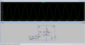
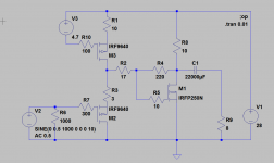
I wanted to build a simple low resistor value Schade feedback Zen amp with a Cree SiC mosfet.
I measured one randomly picked Cree C3M0065090D SiC and one Ixys IXTP32P05T and found that I could easily build something similar to the circuit above. I would use an Ixys IXTP32P05T as M2 and the Cree C3M0065090D as M1.
With some juggling of the values of R1, R2 and R3 I can adjust the amp to a stable working point without altering the feedback ratio in the Schade feedback. With a constant current source instead of R1 (second simulation above) where the 4,7 volt voltage-source should be replaced by a potentiometer, a 5,6 volt zener diode and a resistor to ground to make a adjustable constant current source, the amp will be easily adjustable within a reasonable variation of devices and currents through M1.
I would love to use transformers like Nelson Pass in his 50 watt Zen monster from BAF 2015, but they are expensive compared to a p-channel fet and a few resistors.
The dissimilar sex mosfets will compensate thermally for each other if bolted to the same heatsink.
As an added bonus you get a DC coupled input. No need for large value film capacitors, low input resistance etc.. It would be easy to drive this amp with a SRPP tube preamp or similar, as the input resistance is whatever you use as R6.
Just an idea to play with if you are interested in a simple way of implementing Schade feedback.
Cheers,
Johannes
Last edited:
Inspired by Nelson Pass talk at the BAF 2015 I wanted to rearrange the typical three transistors there is in a Zen amp (gain-device, and the two transistors in the constant current source).
I have been experimenting with the Mu-follower and the Aleph Current source, but decided to "fold" the amp into the constant current source.
It became the same topological layout as the inverted Triadtron I have seen at TubeCad website. Aikido Cathode Follower & More Triadtron
With this basic layout there is a smart way of introduce Schade feedback.
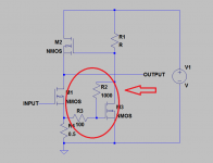
This is the most simplified schematic possible.
R2 and R3 sets the Schade feedback. M2 and M3 is the dominant devices so they will set the general character of the amp. M3 should be a small low powered device like a IRL510 or a Cree C3M0280090D (which is not that low powered, but has a very low Ciss and seems very nice and linear with 500 mA in this application.
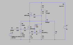
This is the full schematic. (Not optimized).
I have built and listened to Triadtrons before, and they can sound very nice. There are endless possibilities to tune, adjust and modify the circuit. This is only one of them.
According to LTSpice it will have a large output power and very high damping factor for the available voltage and current.
Since I can't run FFT analysis in LTSpice, I can't really say much about the level of distortion.
The amp seems to have a very low output impedance (high damping factor) even without any global negative feedback. The Schade feedback in the current-sensing M3 seems to exert lots of control of the output through the source-follower M2 (simplified circuit at top).
Cheers,
Johannes
I have been experimenting with the Mu-follower and the Aleph Current source, but decided to "fold" the amp into the constant current source.
It became the same topological layout as the inverted Triadtron I have seen at TubeCad website. Aikido Cathode Follower & More Triadtron
With this basic layout there is a smart way of introduce Schade feedback.

This is the most simplified schematic possible.
R2 and R3 sets the Schade feedback. M2 and M3 is the dominant devices so they will set the general character of the amp. M3 should be a small low powered device like a IRL510 or a Cree C3M0280090D (which is not that low powered, but has a very low Ciss and seems very nice and linear with 500 mA in this application.

This is the full schematic. (Not optimized).
I have built and listened to Triadtrons before, and they can sound very nice. There are endless possibilities to tune, adjust and modify the circuit. This is only one of them.
According to LTSpice it will have a large output power and very high damping factor for the available voltage and current.
Since I can't run FFT analysis in LTSpice, I can't really say much about the level of distortion.
The amp seems to have a very low output impedance (high damping factor) even without any global negative feedback. The Schade feedback in the current-sensing M3 seems to exert lots of control of the output through the source-follower M2 (simplified circuit at top).
Cheers,
Johannes
Last edited:
Since I can't run FFT analysis in LTSpice, I can't really say much about the level of distortion.
Just curious, why is that?
Computer (or at least Spice) illiterate.
I fail at math, CAD and Spice. I don't understand why, but I seem unable to understand, despite trying and trying again.
I have been fighting Chronic Fatigue Syndrome for many years. I have a real hard time to focus more then 10 minutes at a time, and I often feel drunk, not in a good way, just the mental fogginess and lack of mental clarity.
Cheers,
Johannes
I have been fighting Chronic Fatigue Syndrome for many years. I have a real hard time to focus
more then 10 minutes at a time, and I often feel drunk, not in a good way, just the mental
fogginess and lack of mental clarity.
Do you sleep normally, and have you tried to get medical help? You shouldn't have to feel like this.
Circlomanen,
I really appreciate your experiments and explanations. Your doing exactly what I've been interested in. I wanted to understand more about the basics of amp design.
I listen to a current source amp, a F2J clone driving smallish full-rangers on OB.
I love it.
I have a couple of designs for a dual driver bottom and, I wondering if PFB would be the ticket...i.e., active.
Johannes - love the imaginative designs and so you are certainly not showing any signs of slowing down mentally !!! As regards the FFT - if you post the .asc, one of us will happily show you how to measure the THD.
Johannes,Inspired by Nelson Pass talk at the BAF 2015 I wanted to rearrange the typical three transistors there is in a Zen amp (gain-device, and the two transistors in the constant current source).
I have been experimenting with the Mu-follower and the Aleph Current source, but decided to "fold" the amp into the constant current source.
It became the same topological layout as the inverted Triadtron I have seen at TubeCad website. Aikido Cathode Follower & More Triadtron
With this basic layout there is a smart way of introduce Schade feedback.
View attachment 539399
This is the most simplified schematic possible.
R2 and R3 sets the Schade feedback. M2 and M3 is the dominant devices so they will set the general character of the amp. M3 should be a small low powered device like a IRL510 or a Cree C3M0280090D (which is not that low powered, but has a very low Ciss and seems very nice and linear with 500 mA in this application.
View attachment 539400
This is the full schematic. (Not optimized).
I have built and listened to Triadtrons before, and they can sound very nice. There are endless possibilities to tune, adjust and modify the circuit. This is only one of them.
According to LTSpice it will have a large output power and very high damping factor for the available voltage and current.
Since I can't run FFT analysis in LTSpice, I can't really say much about the level of distortion.
The amp seems to have a very low output impedance (high damping factor) even without any global negative feedback. The Schade feedback in the current-sensing M3 seems to exert lots of control of the output through the source-follower M2 (simplified circuit at top).
Cheers,
Johannes
Very nice work ! I really like the way you use the gate stopper resistor for part of your Schade network. How did you make the measurements that you mentioned? Thank you for sharing your results with the Cree SiC devices. I am very interested in seeing them used in Schade typologies.
How did you make the measurements that you mentioned?
I am measuring the voltage swing over 4 ohm, 8 ohm and 16 ohm with the same signal in.. A high damping factor does not change the voltage much when changing load.
A negative output impedance increases the voltage over lower resistance loads.
I am also very interested in listening to the Cree SiC fets in a Schade feedback circuit.
Nelson Pass makes a lot of sense in his BAF 2015 talk.
Do you sleep normally, and have you tried to get medical help?
Yes and yes. CFS is a nasty illness. Very debilitating.
Thanks everyone for kind words.
I have been busy trying to learn FFT in LTSpice, and I am making some progress.
I don't know why, but I can never get less then 0,5 percent distortion, regardless of circuit... 😕
I am working on it.
Cheers,
Johannes
CFS is a nasty illness. Very debilitating. I have been busy trying to learn FFT in LTSpice,
and I am making some progress. I don't know why, but I can never get
less then 0,5 percent distortion, regardless of circuit.
Keep looking for help. there has to be a way to get better.
Try simulating a simple resistive voltage divider.
That should be less than 0.5% distortion.
I got the FFT working correctly.
Now I believe in the distortion spectra and the total amount of distortion.
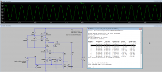
Here is a simple way to create a Schade feedback with a low value resistance feedback network that is easy to drive without transformers or powerful preamps.
It is easy to see the second harmonic dominance originating from the triode character curves with this circuit. I simulated it with two IRF9640 instead of one much more powerful Ixys IXTP32P05T because of the availability in the LTSpice standard library.
I guess the single IXTP32P05T will have less distortion in the same circuit.
It is nice with a DC coupled 100 k input resistance. There is some gate capacitance to consider. With 100 ohm output impedance from the preamp the amp will be down 3 dB at about 230 khz. Good enough for long wave AM transmissions. 😀
Cheers,
Johannes
Now I believe in the distortion spectra and the total amount of distortion.

Here is a simple way to create a Schade feedback with a low value resistance feedback network that is easy to drive without transformers or powerful preamps.
It is easy to see the second harmonic dominance originating from the triode character curves with this circuit. I simulated it with two IRF9640 instead of one much more powerful Ixys IXTP32P05T because of the availability in the LTSpice standard library.
I guess the single IXTP32P05T will have less distortion in the same circuit.
It is nice with a DC coupled 100 k input resistance. There is some gate capacitance to consider. With 100 ohm output impedance from the preamp the amp will be down 3 dB at about 230 khz. Good enough for long wave AM transmissions. 😀
Cheers,
Johannes
Well, nice as always Circlomanen !
Good work, and my usual question... how much poweroutput into speakers?
/ t
Good work, and my usual question... how much poweroutput into speakers?
/ t
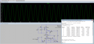
This is a simulation only. Real world results might be different.
I get 21,3 volts over an 8 ohm load (loudspeaker) before clipping.
If I understand how to calculate the output power correctly this is: 21,3/(root of 2)=15,06 volts (RMS). 15,06 squared/8 ohms = 28,36 watts
28 watts power with only 1,1% THD.
Cheers,
Johannes
I was playing around with this P+N device Schade feedback Zen(ish)amp when it struck me that some depletion mode devices could simplify the circuit and make it much more DC stable.
With some IXYS IXTH16N10D2 devices, some simple juggling with the value of the feedback resistors and a greatly simplified solid state Mu follower current source I got this:

And since I have not yet learned to add devices to LTSpice I made an ugly hack with two IRFP250 and two "batteries" to simulate the amp.
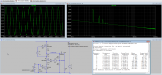
Not spectacularly good simulated distortion performance, but I like the nice balance between second harmonics and third harmonics. I guess It would sound really really good within its usable power range.
Cheers,
Johannes
With some IXYS IXTH16N10D2 devices, some simple juggling with the value of the feedback resistors and a greatly simplified solid state Mu follower current source I got this:

And since I have not yet learned to add devices to LTSpice I made an ugly hack with two IRFP250 and two "batteries" to simulate the amp.

Not spectacularly good simulated distortion performance, but I like the nice balance between second harmonics and third harmonics. I guess It would sound really really good within its usable power range.
Cheers,
Johannes
I would have thought the schade feedback would need to be applied to M1 . At least when I read the zen9 article didn't Nelson say the lower device in a cascode dominated the distortion characteristics ?
the lower device in a cascode dominated the distortion characteristics
Yes.
The P channel source follower (M1) is not included in the feedback loop and whatever distortion it has will be amplified and fed into the speaker.
I made this quick simulation with the same dirty hack Mu-follower as the amp. This is only the P channel follower (M1) with a Mu follower modulated current source.
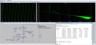
With two volts input signal it has 0,004477% simulated distortion. This is a large enough signal that the amp will be close to clipping anyway, so this small amount of added distortion is quite insignificant (I hope).
Cheers,
Johannes
Since I have been away from electronics for a couple of years I wanted to catch up on all the fun circuits and variations on TubeCAD.
Now I know that the circuit I have been playing with is called the Bastode.
I found some very interesting information and ideas there. I have simulated several of them in LTSpice this last weeks. If I only had found this earlier...
Grid-Cathode Push-Pull Output Stage
More Hybrid-Amplifier Design
Class-A & Current-Dumping & Class-S
He even uses it as faux triode in the same way I am doing in this thread. It is an easy way to implement Schade feedback without bumping into the low resistance Schade feedback values needed to get a low top end distortion from powerful mosfets and their high Ciss.
I am very tempted to buy a couple of Jensen transformers to try Nelson Pass BAF2015 transformer-based Schade feedback. It is an great idea, and I love the sonic character of good signal transformers in audio equipment. I understand the F6 and the M2 sounds very very good, and I have built and tested an single channel of Susan Parkers Zeus amp - which is the best sounding amp I have ever built.
Cheers,
Johannes.
Last edited:
- Status
- Not open for further replies.
- Home
- Amplifiers
- Pass Labs
- Simple Schade feedback without transformer