Post here your tips,tweaks,debugging and things to check
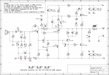
Of this amplifier http://www.diyaudio.com/forums/soli...ple-quasi-complimentary-mosfet-amplifier.html
Of this amplifier http://www.diyaudio.com/forums/soli...ple-quasi-complimentary-mosfet-amplifier.html
Last edited:
D1 and 2 = 1n4004
D4 =1n4002 why not a 1n4004 too
No diference you can use 1N4001-2-4 everywere in this circuit.
Last edited:
Thimios and I have working amps. R5 is 51k. I used 1N4007 for all three diodes and a blue LED for D7. Hugh Dean has some different values for some of the components but that has not been tested.
The 1n400x x=1,2,..7 just means it has higher breakdown voltage with 7 being 1000v. The forward drop is still the same ~0.6v I think.
Well, I am using Aksa's values and they seem to work for me. I just need to add the 220R resistor to my string since I have 500R trimmer and it should let me hit 0v. I am at -23mV but down from -2.5v before so Hugh's values have really been helpful for me. The biggest change was probably use of 1n4148 for the red LEDs.
Hugh Dean has some different values for some of the components but that has not been tested.
Well, I am using Aksa's values and they seem to work for me. I just need to add the 220R resistor to my string since I have 500R trimmer and it should let me hit 0v. I am at -23mV but down from -2.5v before so Hugh's values have really been helpful for me. The biggest change was probably use of 1n4148 for the red LEDs.
OK I misspoke. It has been tested but is not confirmed to work. xrk still has an offset he can not dial out.
Hi mm.
That's very good a Builder Guide- the shortest way with first posts from successful
build Amps.
Nice, thanks!
Cheers.
That's very good a Builder Guide- the shortest way with first posts from successful
build Amps.
Nice, thanks!
Cheers.
Tomorrow I have all the parts so any tips or tweaks would be welcome.
I've the same boards like XRK
I've the same boards like XRK
Offset adjust part have design problem. to get offset near to zero, the base voltage of Q1 will be between -0.55 V to -0.65V.As per the existing design it will between-2.4 to -2.8. you cannot get zero bias. Another issue is VR1 is connected in series with led, Any change in -ve supply voltage will change offset, may be small because R6 is much higher than VR1.But sure it will change.
By very little modification you can get stable 0V offset.
By very little modification you can get stable 0V offset.
Attachments
Sorry , Connect two red LED instead of one LED and a diode to get 0 t0 -1.2V at base of Q1. calculation mistake. Then Voltage across VR1 is -3.6V and Q1 base voltage can vary between 0 to -1.2 V
Last edited:
Good luck guys. I hope you have better luck than me in this board. It is very finicky to get DC offset balanced. Then it is very fragile if your ever short something to the rails. My first unsolvable amp.
This is latest by Thimios:
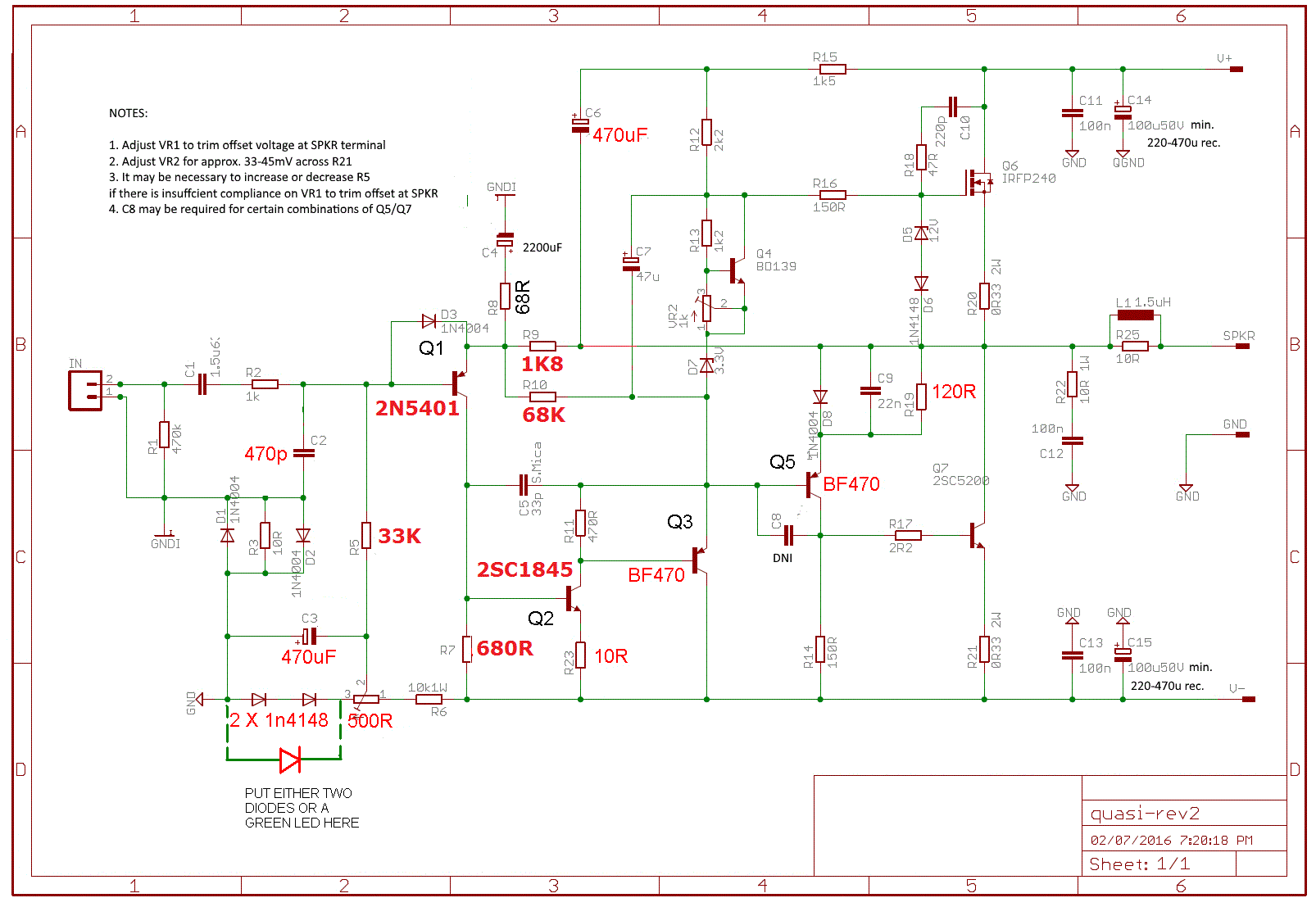
I got mine working based on Aksa's recommendations here:
http://www.diyaudio.com/forums/soli...imentary-mosfet-amplifier-94.html#post4793300
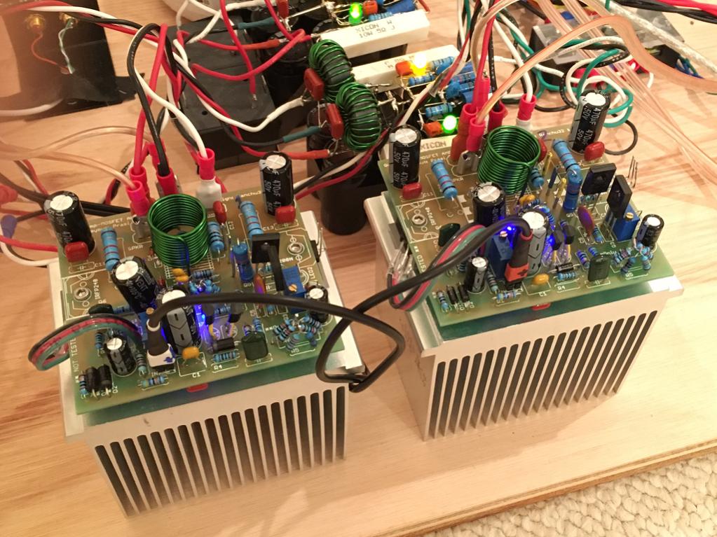
Now sweetly singing in stereo. A wonderful sounding amp.
I got mine working based on Aksa's recommendations here:
http://www.diyaudio.com/forums/soli...imentary-mosfet-amplifier-94.html#post4793300
Now sweetly singing in stereo. A wonderful sounding amp.
just to confirm that this schematic also works for me.
Regards
Thiago,are you using any capacitor parallel to fead back resistor?
Are you using any capacitor at the inverter (DNI)?
What are you using for Q1,Q3,Q5?
Last edited:
Can one of you measure where you trimmer ended up?
Thanks, Terry
I am at about 7R and 14R on one end of trimpot (the end facing 1N4148 diodes).
Thiago,are you using any capacitor parallel to fead back resistor?
Are you using any capacitor at the inverter (DNI)?
What are you using for Q1,Q3,Q5?
parallel capacitor with feedeback is 22pF
CAP DNI is 22pF will try to take .
Q1 is BC560B
Q2 is BC550B
Q3 and Q5 is BF470
- Status
- Not open for further replies.
- Home
- Amplifiers
- Solid State
- simple quasi complimentary MOSFET amplifier BUILDERS GUIDE