OK so X is using 1k8 for R9 and he is at the limit on his 500R trimmer. Thiagomogi, is using 1k5 for R9 and he is close to center on the 500R trimmer. Maybe 1k5 is for R9 a better choice.
Ideally your trimmer will be close to centered. I'm surprised that you don't have more offset drift from cold to fully warmed up. Mine is almost 40mV differential between the two. Maybe I need to insulate Q1 better. It may be heating up along with the rest of the amp. I used short legs on it and with the PCB bolted down to outputs I bet it runs pretty hot. I'll try installing some new transistors for Q1 and leave the legs as long as possible. I want to try Hugh's values anyway, Maybe I should etch a new pair and go all new parts. Then I can compare them better.
Blessings, Terry
Blessings, Terry
My Q1 legs are pretty long (full length). A second amp from scratch would be cool for comparing.
xrk please can you measure again,offset when ampfier is cold,offset when amplifier is warm
DC offset is 40mV at instant turned on from cold, but gets to 20mV within 1 minute of turn on. By 5 minutes it is at 4mV. It's stable within 0mV to 6mV once warmed up.
Latest schematic for Prasi's boards please.
They post all kind of schematics all with different transistors like BF470,2n5401,sc1845 etc.
I don't see the forrest through trees anymore
They post all kind of schematics all with different transistors like BF470,2n5401,sc1845 etc.
I don't see the forrest through trees anymore
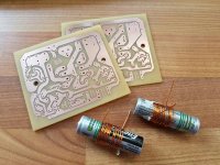
I guess no one feels like making two entries for schematics and BOM as it's in the other thread. I agree there is a lot of activity so tough to follow. But the last weeks' worth of posts pretty much summarizes it. The new layout by Dacz looks pretty nice - you might want to check that out.
Problem is the thread becomes way to big and everbody is using other components and values even try to redesign.
Make a schematic and BOM with all the option of components you can use much easier this way.
Make a schematic and BOM with all the option of components you can use much easier this way.
You might just take the plunge and build the last known working variant rather than waiting for someone to give a complete set of tested plans/ schematics / BOM neatly tied with a bow. It may not happen for this amp. I posted my as built schematic with all parts if you want to go that route. I know it works.
It's just when there're too much different schematics I begin to freak out and doubt sneaks in and don't know anymore which to take.
Hi
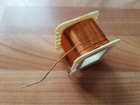
I am starting to gather the components to build this amp and wondered if I could save some money by using the enamel wire from an old crossover.
L1=1.5uH - the build notes suggest 10-15 turns around an AA battery with 1.2-1.5mm wire.
The wire I have is 1mm. Can I increase the number of turns slightly to achieve the correct inductance?
Many thanks
Richard
Attachments
Hi
I am starting to gather the components to build this amp and wondered if I could save some money by using the enamel wire from an old crossover.
L1=1.5uH - the build notes suggest 10-15 turns around an AA battery with 1.2-1.5mm wire.
The wire I have is 1mm. Can I increase the number of turns slightly to achieve the correct inductance?
Many thanks
Richard
Don't worry about it too much - try to get 12 turns around a AA battery and your are close enough.
Don't worry about it too much - try to get 12 turns around a AA battery and your are close enough.
Thanks Xrk! 🙂
- Status
- Not open for further replies.
- Home
- Amplifiers
- Solid State
- simple quasi complimentary MOSFET amplifier BUILDERS GUIDE