I am too old for this.
Where is the complete and accurate schematic of the amplifier?
(So we can see if there is a working combination of 12AT7/12AX7, and plate and cathode resistors, that works in that amplifier)?
And . . .
What are your proposed cathode and plate resistor values for the 12AT7?
What are your proposed cathode and plate resistor values for the 12AX7?
12AT7 u = 60, rp = 10.9k, Gm = 5500 microMhos.
12AX7 u = 100, rp = 62k, Gm = 1600 microMhos. . . . Very little current capability
As long as you are tube rolling dual triodes with 9A pinouts, don't you want to try:
12AU7
12AV7
12AY7
12AZ7
And
12BH7 . . . you wanted current drive capability, right?
Be sure to have enough filament current for some of the above tubes, so the 6.3V secondary does not overheat.

I am too old for this.
Where is the complete and accurate schematic of the amplifier?
(So we can see if there is a working combination of 12AT7/12AX7, and plate and cathode resistors, that works in that amplifier)?
And . . .
What are your proposed cathode and plate resistor values for the 12AT7?
What are your proposed cathode and plate resistor values for the 12AX7?
12AT7 u = 60, rp = 10.9k, Gm = 5500 microMhos.
12AX7 u = 100, rp = 62k, Gm = 1600 microMhos. . . . Very little current capability
As long as you are tube rolling dual triodes with 9A pinouts, don't you want to try:
12AU7
12AV7
12AY7
12AZ7
And
12BH7 . . . you wanted current drive capability, right?
Be sure to have enough filament current for some of the above tubes, so the 6.3V secondary does not overheat.
The circuit is included in the attached PDF - it's a large schematic so might be easier to read on PC/tablet than a phone.
Further info here:
https://www.redrookits.com/stereo-amplifier/
Here is a thread which the designer, a fellow Aussie Phil Wait, posted when he first launched the kit circuit.
https://www.diyaudio.com/community/threads/new-redroo-tube-amplifier-from-australia.373538/
As I have quite a number of 12.6V dual triode valves I thought it would be worth spending the time to optimise the system.
Attachments
You said the gain [of the first stage] did not matter. You wanted a 9A pinout.
If you want to use a cathode follower to drive current into an EL34 control grid . . .
Your choices are:
12BH7 u =16.5; 20mA max; 3.5 Watt Diss. plates; 200V K-F; and 3100 uMho (935 Ohms cathode impedance).
12AT7 u = 60; 15mA max; 2.5 Watt Diss. plates; 90V K-F; and 5500 uMho (182 Ohms cathode impedance).
ECC99 u = 22; 60mA max; 5 Watt Diss. plates; 200V K-F; and 9500 uMho (105 Ohms cathode impedance).
Probably your best bet.
Think about:
1. A cathode impedance of 935, 182, or 105 Ohms that is driving an EL34 control grid, g1, Which is probably between 200 Ohms and 500 Ohms in A2.
2. An EL34 screen, g2, that is going to draw Lots of screen current when g1 is driven that hard. Look for a red screen.
Let us know how it works for you.
@6A3sUMMER we were just writing at the same time, schematic is now attached above.
Note, there are jumpers on the PCB for using 6.3V dual triodes so using 6DJ8, 6H30pi, etc is an option, too.
Note, there are jumpers on the PCB for using 6.3V dual triodes so using 6DJ8, 6H30pi, etc is an option, too.
lordearl,
I was still editing my Post # 24 when you posted the schematic.
I needed that schematic in Post # 1.
I very much like the amplifier you picked to build.
Looks like a well designed circuit, and looks beautiful too.
But . . .
That amplifier does not go into A2, unless you want to have large bias shifts on the EL34 output tube.
The Cathode Follower drives an RC coupling to the grid, g1 of the EL34 (That causes bias shift the moment you draw grid current).
And bias shift might not be so bad in a transient moment, except for the time it takes for the bias shift to go away as the music quiets down.
It takes about 48 milliseconds to get rid of 63% of the bias shift voltage.
Given no global negative feedback; no output tube cathode negative feedback; and no Schade negative feedback; then . . .
An EL34 in pentode mode has the highes power, highest distortion, and Lowest damping factor.
An EL34 in Triode Wired mode has the lowest power, lowest distortion, and highest damping factor.
And for an EL34 in Ultra Linear mode has medium power, medium distortion, and medium damping factor.
(All relative).
. . . But your Ultra Linear outputs can either Have global negative feedback for even lower distortion and higher damping factor,
or no global negative feedback.
Have fun building and listening!
Last edited:
Thanks @6A3sUMMER, agree, it's an excellent design - will report back on the sound.
The designer seems confident it goes into Class A2 so I will check with him.
I'm building it in Triode Mode, hence the queries around sensitivity and the most appropriate valve for the input stage. 👍
The designer seems confident it goes into Class A2 so I will check with him.
I'm building it in Triode Mode, hence the queries around sensitivity and the most appropriate valve for the input stage. 👍
This was an interesting paragraph in the build instructions above ... I don't recall seeing this argument before, but it looks plausible. I suppose this could be a guitar amplifier designer's view on the world, and a well designed audio amplifier is designed with sufficient headroom for all signal levels.
There is another important reason why a large amount of global negative feedback is not a good idea, especially when applied to valve amplifiers using output transformers - the slowest responding component in a valve amplifier is usually the output transformer and, as the output transformer is usually within the feedback loop, it mostly determines the speed (response time) of that feedback-loop.
Imagine a circuit where there is 20dB of negative feedback, so the Feedback reduces the voltage amplification (gain) of the entire circuit by 10 times. During the delay period, before the feedback takes effect, the gain of the circuit would be 10 times higher, and the amplifier would be forced into into overload and hard distortion (clipping) by a very modest input signal.
" Imagine a circuit where there is 20dB of negative feedback, so the Feedback reduces the voltage amplification (gain) of the entire circuit by 10 times. During the delay period, before the feedback takes effect, the gain of the circuit would be 10 times higher, and the amplifier would be forced into into overload and hard distortion (clipping) by a very modest input signal. "
I did not understand anything 🤔
I did not understand anything 🤔
This is prevented by an input filter that removes frequencys below or above the audio band.This was an interesting paragraph in the build instructions above ... I don't recall seeing this argument before, but it looks plausible. I suppose this could be a guitar amplifier designer's view on the world, and a well designed audio amplifier is designed with sufficient headroom for all signal levels.
Typically a cap at input preventig subsonics and a cap removing ultrasonics.
Was chiming in to suggest same as Rayma did, I use them a lot for your exact same use: offer different, user selectable resistors and capacitors,to provide different biasing, load, gain, EQ, etc. ; only extra is that I use the shorting jumpers which come with a stub or tongue so user can easily pull and replace them with his bare fingers, no long nose pliers needed.Very clever!
I'm surprised there isn't a sort cartridge style PCB receptacle that allows resistances to be changed with a small switch of some description...
Or long and hard nails 😱
https://www.digikey.com/en/products/detail/sullins-connector-solutions/NPC02SXON-RC/2618266
I use them a lot to avoid users butchering my PCBs with poor soldering and desoldering technique when their fingers get itchy to try different sounds, also because I am a fan of Russian 6N2P tubes, in my view an improved 12AX7 on steroids, built for Military and Industrial use ... but Musicians love to do their tube rolling thing, so ....
I do NOT trust Dip switches at Tube voltage levels, this is safer.
This was an interesting paragraph in the build instructions above ... I don't recall seeing this argument before, but it looks plausible. I suppose this could be a guitar amplifier designer's view on the world, and a well designed audio amplifier is designed with sufficient headroom for all signal levels.
This notion of "time delay" in a feedback circuit has been discussed many times here in this forum. There is no "time delay," only phase shifts. There are reasons to prefer a non-feedback amp to one with feedback, but "time delay" is not one of them.
Hi.
Phil from Red Roo Kits here. Interesting discussion and I'm chuffed there is some interest in the amp.
One thing I would like to clear up though - I think the low-impedance from the cathode follower would only be beneficial around the point where the output tubes first start to draw small amounts of grid current.
I'm thinking It could also be useful with older output tubes that may have reduced vacuum and in tubes where there is some 'initial' grid current flowing in the negative grid voltage region.
With average sensitivity loudspeakers operating at reasonable volumes on a 5W RMS amp, music peaks are very likely to be clipped. My thinking is the progression into clipping may be a little more gentle, but I haven't been able to confirm that.
Interesting ideas about selecting resistors. My initial thought was that the market for this amp would be general electronics hobbyists, rather than audiophiles, so at the time I was more concerned about ease of construction rather than ease of modifications. I'll keep this in mind for the next PCB revision.
Interested in your thoughts.
petertub,
Probably the greatest low pass filtering effect in that amplifier is the 1 nanoFarad cap, C4, from the Screen to the Plate (Plate to UL Tap).
I wonder how much ringing that 1 nanoFarad cap causes with [60% ?] of the primary winding.
And there is the capacitor, C5, across the negative feedback resistor.
If I got the capacitor numbers wrong, correct my bad eyes.
The low frequency rolloff response causes I see are:
The RC coupling from cathode follower to output tube grid g1
The capacitor that is across the self bias resistor in the output stage
The output transformer's primary inductance
I do not think that the 50K volume control and grid stopper resistor interacting with the input tube's miller effect capacitance do much filtering below LF radio frequencies.
And I do not think the grid stopper on the output tube and its miller effect capacitance has much effect below LF radio frequencies.
Sorry that I can not read the resistance and capacitance values on the schematic.
Sorry that my analysis powers are quickly degrading with my mini-strokes.
That is all I saw on schematic in Post # 28.
The basic rule for Clipping . . .
Turn the volume down, to fix it for the time being,
then go to your computer, and order a new amplifier with 3dB, or better yet, 10dB to 20dB more power output.
Turn the volume down, to fix it for the time being,
then go to your computer, and order a new amplifier with 3dB, or better yet, 10dB to 20dB more power output.
This notion of "time delay" in a feedback circuit has been discussed many times here in this forum. There is no "time delay," only phase shifts. There are reasons to prefer a non-feedback amp to one with feedback, but "time delay" is not one of them.
A negative linear phase shift with frequency is indistinguishable from a time delay.
If a first order, low pass amplifier has much greater bandwidth BW than the input signal,
then the amplifier's effective time delay for that signal is -1 / BW , where the bandwidth BW is in Hz.
This effect is sometimes called "integrator delay".
Explanation:
For a perfect first order, low pass amplifier, the phase shift is -arctan ( f / BW )
This is approximately linear for a signal f much less than the bandwidth BW,
when -arctan ( f / BW ) becomes nearly ( -f / BW ) , since arctan(x) ~ x for small x.
Then d (phase) / df = d ( -f / BW ) / df = -1 / BW which is a negative, constant time.
This linear phase -f / BW is equivalent to a time delay of -1 / BW seconds.
So if a 1MHz bandwidth single pole low pass amplifier is used for audio,
the audio signal time delay in the amplifier is -1 / 1MHz which is 1uS.
The period of 20kHz is 50uS long.
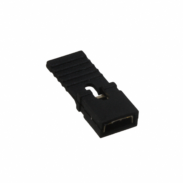
None of my boards nearby ("Sunday" 😉 ) but a couple Net pictures:Thanks @JMFahey this looks like a good approach. Any chance you can show a few photos of these in action on a board as I can't quite picture how the system works. Thx in advance!
Imagine you build a singe triode stage, want to select:
- plate resistors 47k or 100k
- Cathode resistors 1k5 or 820 ohm
- Cathode capacitors: 10uF / .68uF / none
plenty options for tube rolling, huh? 😉
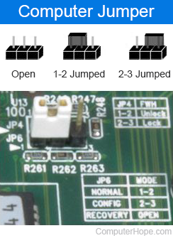
Call pins 1 - 2 - 3 left to right
* For plates: put 2 resistors side by side; join 1 end which goes to tube plate.
Free ends go to pins 1 and 3 ; pin 2 goes to supply (say +200V)
Now you can choose either 47k (1 - 2) or 100k (2 -3)
* For cathode resistors: resistor junction goes to ground, 1k5 to pin 1, 820 ohm to pin 3, pin 2 to tube cathode, connect what you want.
* for cathode capacitors: same thing:
10uF to pin 1, .68uF to pin 3, pin 2 to cathode.
I can choose either cap or none at all , by not putting the jumper.
Way more flexible that switches ... did I say Cheap? 😉
Strong enough for 200V or more, and significant current, one such jumper system is used in PC suppies switching between 120V and 240V Mains, go figure
The jumper mentioned here is same size and type as shown above 😱 :

Mark Bass amplifier uses 2 jumpers and 3 pin pairs (CN1 CN3 CN6) to select 100V Japan, 120V/220V/240V US/Europe mains.
These little beasts are versatile and strong.
Again: cheap!!!
Meaning you can use as many as you wish in your boards.
Last edited:
- Home
- Amplifiers
- Tubes / Valves
- simple method for changing plate/cathode resistors on PCB