Hi all
I learnt a few thing over the last few weeks
1. all my old amps really suck the technics especially
2. old amps pick up niose from my pc
3. stacking speakers is cool
4. biamping done right rocks(maybe some dampening in my bright room)
5. the pc fan is getting on my nervous now
6. im gonna need another ska or two the 150 and 300
7. i was quite happy bieng ignorant But im happier now
yup
This is a great amp.I still need better speakers or mods,And we havent done the dali thing yet. But we will get around to it.
It so clean and clear sounding in the well every configuration i tryed
I hooked my vintage technics speakers 3 way sealed with the plastic grills.These are dead standard everything still work great.
But I wanna change the crossover`s and some decent wire and terminals.
and threw them upside down on the jvc sk-1000 cabs on stands so the tweeter is at ear level
got rid of the technics amp and cleaned the pioneer up
crossed at 300hz with foobar.
pioneer vsa-700 running 300 and under
I swear i`ve got more power than this room can handle now.With greater clarity the volume just a bonus
,And with my earlier listening tests i cant wait to throw the pioneer on the stack of crap too sell on ebay.
and replace it with another ska
I would have to say im the happiest ive ever been with my personal setup still a few tweaks needed but im content to listen for awhile.and continue to improve things slowly
thanks all for reading my ramblings
hope they made some sence!
morbo!
Matt,
Glad you like the amp.
I am sure Greg would be pleased by your comments, welcome to real audio.
Macka
Glad you like the amp.
I am sure Greg would be pleased by your comments, welcome to real audio.
Macka
rellum said:Hello,
Yesterday I've increased Iq to run one channel at 1.4A and replaced input RC
filtering caps with some silver mica 100pf/500V caps. Good overall
stability. No overrun. Exemplary offset stability. To perform
some comparisons, I decided to run one channel AB and the other class A. I
made some mono listening tests yesterday evening with manual swapping. First
impressions : no changes. Tomorrow, I connected my switcher. It's a self
made one with wired remote controled relays. Many contacts are in parralel,
the off contacts feed a dummy load to keep each amp allways loaded and
ground is also switched to avoid ground loops. The only change that I
noticed when swapping is in the bass region. No more
impact but a fuller bass sound, with slightly more energy. I connected my
scope at the inputs of the amps and with the ADD+INVERT mode had a flat line
in the middle. Connecting the probes on the speaker outputs, the flat line
is somewhat modulated but at low frequency only.
The less efficiency of the bootstrap caps at LF gives less open loop gain
and thus, increase the output impedance. It wasn't noticeable on two way
speakers or with a low bass content on my own one.
In class A, higher transconductance of the output mosfets gives some more
gain that allows for that bass extension. Clearly, this amp has nothing to
gain with class A. Energy waste.
The bootstrap caps could be replaced with some biggers and best quality. The
P mosfets could be replaced with some IRFP9140. Sadly, I have only two of
them on hand and they are not easy to provide.
A more clever solution could be to add an error correction circuit. But not
an Hawksford one, output stage has gain here. Why not an opamp based one
wich action could be limited to the low frequency range ? A bass extender
could also do a nice job...
This amp is clearly a HIGH FEEDBACK design, but a clever one.
Won't suit everybody's taste.
To summarize, it combines : low cost, high power if needed, very low
distorsion, good definition and an incredible softness wich allows for long
listening sessions.
Cheers,
Francis
Hi Francis,
i ask Greg about opinion of Hiraga Mostre amp, and he told me that you are familiar with this amp.
Could you opinion also for Monstre amp?
I build Monstre amp with 4 regulators (ultimate mini regulator using 5200 transistors, OPA627) and 5200/1943 transistors.
My speakers are high sensitive Siemens fieldcoil type in open baflle.
regards, Bostjan
rellum said:...
This amp is clearly a HIGH FEEDBACK design, but a clever one.
Won't suit everybody's taste.
.....
Cheers,
Francis [/B]
hi rellum / Francis,
After using my stereo 300D for quite a while now, and having built another pair of 150D for a friend (where it is running almost 10..14hs/day...), who was marvelled by its sonic performance, I am now assembling the next pair of 300D for his son, a rock musician with very sensitive ears when it comes to resolution and naturalness of reproduction, for his mixing console.
I have to agree, that the ingenuity of Greg's clever design is definitely a high gain/feedback system: without the I/P filter and driven by a 150 Ohm source: a quick simulation of the 300D, done by a friend of mine shows an interesting O.L./freq plot: 1 to 10 Hz flat with 70dB gain, then slanting upwards at 20 dB/dec to impressive 96.5dB of gain at around 200 Hz, then flat to 10 kHz(!), decreasing slowly at 20db/dec onwards. At 100 kHz still some neat 77 dB of gain left. Phase response is fairly a flat slanting line of -90deg/decade from 50 Hz..5MHz.
Changing the bootstrap caps from 10 to 47uF lifts the lower end gain. This change is best visible when closing the loop for a 29dB gain figure: the lower end curve which, with 10uF caps dropped by 0.08dB (!) at 1 Hz (no caps in the feedback network), now pushes the slanting downwards point in the curve way out downwards. This surely will reflect in an improved bass behaviour (damping factor). The bootstrap caps play a vital role in this design, lifting the O.L. gain in the 10Hz..10kHz region by some 26dB. The overall closed loop -3dB point is somewhere around to 1 MHz. The cap bridging the 27k feedback resistor had to be increased to 6.8 (orig. 5.0) pF for a smoother curve above 200kHz (no peaks). -1 dB point is @ some 700 kHz. Bridging the bootstrap caps with some 100nF foil caps surely will impact positively in the quality at the upper freq end. The phase response closed loop is 0 deg to 20 kHz, -47 deg @1 MHz, then diving onwards. To remember: All these simulations done w/out input low-pass RC-filter.
In summary: this is also a HIGH-SPEED design (thanks to the MOSFET output stage in common source config), castrated in BW by the input RC LP filter. Thus, the impedance of the driving cct must be well taken into account. Otherwise your –3dB point will move to a lower point in frequency. Better keep source impedance below 150 Ohms, if possible. Reducing the 1nF input filter cap and replacing it by something around 470pF (no ceramics pse!, good foil cap or silver-mica are best), could improve the upper end freq range quality. This mod increases its sensitivity to RFI/EMI. So, make neat, clean wirings, twist your signal lines, follow Geg’s instructions on how to wire the DC power wiring and, last but not least, provide a good AC mains input filter.
My policy with audio power amps is to pay special attention to the power supply issue. Plenty of DC power should be available. It makes no sensible use bargaining here! In fact, my costs plan shows a 40/60 relationship between the modules themselves and the whole rest of necessary hardware (trafos, cases, DC filter caps etc, etc.)
There is too much bothering noise on the AC power lines that creeps over the pwr xfmrs onto the DC supply voltages. Due to the high PSRR of Greg’s design the noise most probably will enter the signal path via capacitive or magnetic coupling somewhere else in the wiring.
Another thing: Tame those horrendous toroidal’s inrush currents by a simple inrush current limiting cct, such as elektor's 974070 delay cct. Your DC filter caps and rectifiers will thank you with a longer life, as well no more runs to the AC home distribution panel to re-close that tripped cct breaker.
So long, hope more diy audio aficionados discover this jewel of audio power amp for themselves. 😀
stoeffle.++++
Great Work Stoeffle,
This is the sort of testing that advances understanding of the design and possible areas which could benefit from tweaking.
Your tests bring the modders focus to
"the feedback cap - better quality & change value to 47uF - should help the low end (improved damping & bass behaviour)
Bypass this cap with 110nF good quality film/foil should help the top end.
27K feedback resistor - increase bypass cap from 5pF to 6.8pF may also help the top end?
Reduce the input filter cap from 1nF to 470pF foil or silver mica will improve the top end."
I have done some of these mods(on a 150D) with success
- replaced C9 feedback cap with Panasonic FC 47uF (hardly noticable turn on pop with ineffecient speakers - Rogers LS3/5a's)) - any higher will probably give a noticable pop - will try bypassing as you suggest
- reduced input filter cap to 150pF styrene (this value was recommended somewhere?)
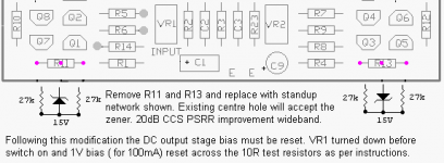
- implemented the zener mod
After above mods a definte improvement in top end (speakers do not go very low so not so noticable bass improvement)
But, I did notice some skitishness in the amp - more hiFi'ish not as silky smooth.
This was solved when I changed the grounding scheme - instead of wire to ground from cap bank I implemented Gregs recommended grounding through 10R 1 W resistor with paralled diodes (1 reversed). This could well have been the EMI/RFI sensitivity you mentioned.
Just thought these points might help fufture modders.
John
This is the sort of testing that advances understanding of the design and possible areas which could benefit from tweaking.
Your tests bring the modders focus to
"the feedback cap - better quality & change value to 47uF - should help the low end (improved damping & bass behaviour)
Bypass this cap with 110nF good quality film/foil should help the top end.
27K feedback resistor - increase bypass cap from 5pF to 6.8pF may also help the top end?
Reduce the input filter cap from 1nF to 470pF foil or silver mica will improve the top end."
I have done some of these mods(on a 150D) with success
- replaced C9 feedback cap with Panasonic FC 47uF (hardly noticable turn on pop with ineffecient speakers - Rogers LS3/5a's)) - any higher will probably give a noticable pop - will try bypassing as you suggest
- reduced input filter cap to 150pF styrene (this value was recommended somewhere?)
- implemented the zener mod
After above mods a definte improvement in top end (speakers do not go very low so not so noticable bass improvement)
But, I did notice some skitishness in the amp - more hiFi'ish not as silky smooth.
This was solved when I changed the grounding scheme - instead of wire to ground from cap bank I implemented Gregs recommended grounding through 10R 1 W resistor with paralled diodes (1 reversed). This could well have been the EMI/RFI sensitivity you mentioned.
Just thought these points might help fufture modders.
John
That's a great write-up on the SKA amps Stoeffle. Greg has certainly come up with a breakthrough design.
My GB150 is magnificent , hard to better at any price.
My GB150 is magnificent , hard to better at any price.
Hey Stoeffle,
Have you done any of these mods? - Any sonic improvements to report?
I posted to Greg but he imagines that mods will be inaudible, in theory. However, would be interested to get feedback.
Regards
John
Have you done any of these mods? - Any sonic improvements to report?
I posted to Greg but he imagines that mods will be inaudible, in theory. However, would be interested to get feedback.
Regards
John
Warning
THIS AMPLIFER SHOULD NOT BE USED INCONJUNCTION WITH T.H.C
may cause prolonged periods of bliss
followed by auditioury hallutionations
greg
i think you better attach this to future models!
THIS AMPLIFER SHOULD NOT BE USED INCONJUNCTION WITH T.H.C
may cause prolonged periods of bliss
followed by auditioury hallutionations
greg
i think you better attach this to future models!
I think there are, except for 'scientific' purposes.
But there's no OZ laws against designing great new SKpreamps -
http://www.diyhifi.org/forums/viewtopic.php?p=17891#17891
I'm picking up my kits today.
But there's no OZ laws against designing great new SKpreamps -
http://www.diyhifi.org/forums/viewtopic.php?p=17891#17891
I'm picking up my kits today.
zener mod
Did the zener mod today after 6 months of listening to the unmodded version - just finished listening for about an hour. I wouldn't have thought it possible to improve on the really sweet combination of the original amp and ellisaudio 180b speakers but this seems a worthwhile improvement after the listening session. Auditory memory can be fleeting but there is one objective improvement to bolster the subjective impressions - the ear on tweeter test shows the modded amp to be pretty much silent where the previous had a faint hiss audible at about 2-3 inches (5-7cm).
rez
jkeny said:Great Work Stoeffle,
This is the sort of testing that advances understanding of the design and possible areas which could benefit from tweaking.
Your tests bring the modders focus to
I have done some of these mods (on a GB150) with success
- the feedback cap - better quality & change value to 47uF - should help the low end (improved damping & bass behaviour). Bypass this cap with 110nF good quality film/foil should help the top end.
- 27K feedback resistor - increase bypass cap from 5pF to 6.8pF may also help the top end?
- Reduce the input filter cap from 1000pF(1nF) to between 150pf/470pF foil or silver mica will improve the top end."
After above mods a definte improvement in top end (speakers do not go very low so not so noticable bass improvement). But, I did notice some skitishness in the amp - more hiFi'ish not as silky smooth.
- replaced C9 feedback cap with Panasonic FC 47uF (hardly noticable turn on pop with ineffecient speakers - Rogers LS3/5a's)) - any higher will probably give a noticable pop
- will try bypassing as you suggest
- reduced input filter cap to 150pF styrene (this value was recommended somewhere?)
- implemented the zener mod
This was solved when I changed the grounding scheme
Just thought these points might help future modders.
- instead of wire to ground from cap bank I implemented Gregs recommended grounding through 10R 1 W resistor with paralled diodes (1 reversed). This could well have been the EMI/RFI sensitivity you mentioned.
John
Hi rez
Here are some other mods to try, mentioned by Stoeffle and tried by John
thanks
KL
Hi
470pF is slightly low for sources <500r (1k0+500r * 470pF=0.7uS)
680pF to 1000pF is more suitable for sources <100r (1k0+100r * 680pF=0.75uS)
the 150pF is ONLY appropriate with a HIGH source resistance.i.e. unbuffered attenuator. (0k47+2k5 * 150pF=0.45uS)Reduce the input filter cap from 1000pF(1nF) to between 150pf/470pF foil or silver mica will improve the top end."
470pF is slightly low for sources <500r (1k0+500r * 470pF=0.7uS)
680pF to 1000pF is more suitable for sources <100r (1k0+100r * 680pF=0.75uS)
AndrewT said:Hi the 150pF is ONLY appropriate with a HIGH source resistance.i.e. unbuffered attenuator. (0k47+2k5 * 150pF=0.45uS)
470pF is slightly low for sources <500r (1k0+500r * 470pF=0.7uS)
680pF to 1000pF is more suitable for sources <100r (1k0+100r * 680pF=0.75uS)
Hi Andrew
Could you to explain these values
- 0k47+2k5
- 1k0+500r
- 1k0+100r
KL
I dont know what mods been done to mine
But i had my brother around the other day
He thought i was going nuts,untill i put the volume controll in his hand and told him he was in charge
the next time i seen his face he had a look of shock and pleasure blasted on(shock i wasnt going crazy)the pleasure obvious
My mom two,I gave her a test listen and she was amazed
Next the stepfather he has to get his butt down here and listen
Im saving up for a few more pre built boards(last thing i soldered was a smart card reader writer)
And im sure greg will do a better job than me
Ian where did you get the case all the other extra`s? i want the same look
I wanna try too put together a 150
if that works i will put together a 300 for the step
I gotta give the poineer a good whacking every now and then to keep it`s running not gonna last much longer
I will be contacting you sooner or later greg!
the more i listen the more i wanna listen
the thing runs for 12 hours a day
I feel like ive been an underprivileged kid all my life and didnt even know it.yeah i had good toys none as good as this!
Hi,
for a gb150
R2=1k0 when Rs is low (<200r).
R2 should be reduced or shorted out when Rs is high (<200r).
second resistance is Rs
third is C2
Rs is usually in the range 47r to 220r but can exceed 1k0 depending on the design of the source output impedance.
An unbuffered attenuator has a variable output impedance that varies from near zero ohms to Zin/4 when set to -6db ( there is a small correction for Rs from the real source).
That is the problem with all unbuffered attenuators. Variable Zin and/or Zout. A 10k pot set to -40db will have the lower leg @ about 100r and the upper leg @ about 9900r The output impedance (when Rs=200r) = 100//[9900+200]= 99r.
the RF filter will be set to about 99r+470r*150pF=0.09uS. that is too little filtering.
That I see as a problem, almost no filtering when used at low to medium volume settings.
when set to high volume the filter is more effective.
that's the figure I quoted at the beginning.
Note, setting R2=0 is an even bigger mistake.
for a gb150
R2=1k0 when Rs is low (<200r).
R2 should be reduced or shorted out when Rs is high (<200r).
first resistance is R2.the 150pF is ONLY appropriate with a HIGH source resistance.i.e. unbuffered attenuator. (0k47+2k5 * 150pF=0.45uS)
470pF is slightly low for sources <500r (1k0+500r * 470pF=0.7uS)
680pF to 1000pF is more suitable for sources <100r (1k0+100r * 680pF=0.75uS)
second resistance is Rs
third is C2
Rs is usually in the range 47r to 220r but can exceed 1k0 depending on the design of the source output impedance.
An unbuffered attenuator has a variable output impedance that varies from near zero ohms to Zin/4 when set to -6db ( there is a small correction for Rs from the real source).
That is the problem with all unbuffered attenuators. Variable Zin and/or Zout. A 10k pot set to -40db will have the lower leg @ about 100r and the upper leg @ about 9900r The output impedance (when Rs=200r) = 100//[9900+200]= 99r.
the RF filter will be set to about 99r+470r*150pF=0.09uS. that is too little filtering.
That I see as a problem, almost no filtering when used at low to medium volume settings.
when set to high volume the filter is more effective.
that's the figure I quoted at the beginning.
Note, setting R2=0 is an even bigger mistake.
- Status
- Not open for further replies.
- Home
- Amplifiers
- Solid State
- Simple Killer Amp - Listening impressions