Hi,
what waveform are you inputting?
BTW 15% regulation with a resistive load (no rectifier) is very bad, even for an EI.
5% to 6% is good and most can achieve this in the rating you are probably using.
Bigger transformers can achieve 4% and even less.
what waveform are you inputting?
BTW 15% regulation with a resistive load (no rectifier) is very bad, even for an EI.
5% to 6% is good and most can achieve this in the rating you are probably using.
Bigger transformers can achieve 4% and even less.
Hi AndrewT
This is also the case for the measurements presented on attachment of post#318.
The transformer is connected to two GB150S PSU modules, the PSU modules connected each to one GB150U amplifier module and each amp. module connected to 6 Ohm 170 W dummy load. Data refers to a working amplifier the configuration of which is reported on posts #305 and #306
Regards
George
Input is sinusoidal (see post#318)what waveform are you inputting?
Andrew, my remark of 15% was refering to a transformer connected to a rectifier bridge plus smoothing capacitors plus consumption (load).BTW 15% regulation with a resistive load (no rectifier) is very bad, even for an EI.
This is also the case for the measurements presented on attachment of post#318.
The transformer is connected to two GB150S PSU modules, the PSU modules connected each to one GB150U amplifier module and each amp. module connected to 6 Ohm 170 W dummy load. Data refers to a working amplifier the configuration of which is reported on posts #305 and #306
Regards
George
Strange looking Amplifier, Electrical data 2
Frequency Response measurement.
Manual method.
Sinusoidal Oscillator output impedance 50 Ohm.
Dummy load 6 Ohm
0dB: 800mVpp on 6 Ohm ~16mWrms, both channels driven.
Freq Response
(Hz) (dB)
10Hz -1.41dB
20Hz -0.9 dB
50Hz -0.67 dB
100Hz 0 dB
. .
. .
. .
100KHz 0dB
200KHz -0.33dB
500KHz -4.6dB
1MHz -15.6dB
Greg Ball reports 20Hz-20Kz + 0dB, - 0.25dB. This small difference (0.65db) in low freq. is insignificant and probably attributed to difference in set-up. I will recheck it when I will do automatic (PC) measurements.
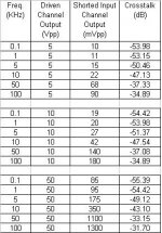
Interchannel Crosstalk .
Interchannel Crosstalk .
This is an important topic, as the two PSUs are fed from a common transformer.
Test accomplished by shorting the input of one channel and driving only the other channel.
The output of both channels (loaded by 6 Ohm dummy load) recorded.
Crosstalk (dB)=20*log (shorted-input channel output / driven channel output).
Observation 1: Crosstalk drops off considerably at higher frequencies.
Observation 2: Crosstalk is independent of power output (observed differences are attributed to the heating of the dummy load)
Attachments
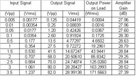
Input-Output relationship
Input-Output relationship
Both channels driven (1KHz sinusoid). Dummy Load 6 Ohm.
Amplifier gain is 28dB.
Observed slight increase in gain at higher power is attributed to the heating of the dummy load.
Linear region is up to 140-150 Wrms. Beyond that, clipping commenses ( clipping becomes visible on oscilloscope above 170 Wrms).
Regards
George
Attachments
Hi,
those scope traces are so far from sinusoids that I did not recognise them as such.
It appears you have clipping and sticking and slewrate limiting all combined.
Try less input voltage and lower frequency to see if the output at least resembles a sinusoid.
BTW. that -0.9db @ 20Hz indicates a problem of overlooked DC blocking somewhere. Find it and sort it.
Hi Andrew
If you are refering to the scope traces attached on post#319, then, please note the text embeded on the photos. The photos do not show amplifier's sinusoidal output signal. They show the ripple which is superimposed over the DC +/- rails of the Power Supply Unit (PSU).
I have to repeat the frequency response measurement to confirm if there is really a decline in response or it is a measurement artefact. I will report back.
Regards
George
those scope traces are so far from sinusoids that I did not recognise them as such. It appears you have clipping and sticking and slewrate limiting all combined.
If you are refering to the scope traces attached on post#319, then, please note the text embeded on the photos. The photos do not show amplifier's sinusoidal output signal. They show the ripple which is superimposed over the DC +/- rails of the Power Supply Unit (PSU).
BTW. that -0.9db @ 20Hz indicates a problem of overlooked DC blocking somewhere. Find it and sort it.
I have to repeat the frequency response measurement to confirm if there is really a decline in response or it is a measurement artefact. I will report back.
Regards
George
Hi Andrew T
They show the voltage at the secondary of the power transformer (actually half of the voltage, center tap to end of one coil) .
An ideal x-former would produce a pure sinusoid (assuming utility's voltage is a sinusoid).
None of the x-formers I have tested produce a sinusoid. All of them flatten at the top and bottom.
In fact, the less inductance (turns/volt) they excibit at the primary, the more they flatten.
Toroids I have tested are worse than E-I on this.
Once, I asked from a local x-former maker to wind 3 E-I x-formers with the same output specifications. The difference would be on the turns/volt of the primary (thus inevitably on the turns of the secondary as well). The one would have the turns/volt he was regularly using. The other two would have 10% and 20% more.
When I tested them with the oscilloscope, the one with 10% more turns at the primary still had some flats. The one with 20% more turns at the primary was almost flatless, but certainly still not a pure sinusoid.
As for the "sticking" that I have marked on the traces, it is where (more or less) damped oscillations show up. They are triggered at the moment the rectifying diodes switch on and off.
Regards
George
Oh, you were refering to the scope traces of post#320. Then these traces do not show amplifier's sinusoidal output signal.post 320 showing clipping, slew rate limiting and sticking. You have highlighted the sticking.
They show the voltage at the secondary of the power transformer (actually half of the voltage, center tap to end of one coil) .
An ideal x-former would produce a pure sinusoid (assuming utility's voltage is a sinusoid).
None of the x-formers I have tested produce a sinusoid. All of them flatten at the top and bottom.
In fact, the less inductance (turns/volt) they excibit at the primary, the more they flatten.
Toroids I have tested are worse than E-I on this.
Once, I asked from a local x-former maker to wind 3 E-I x-formers with the same output specifications. The difference would be on the turns/volt of the primary (thus inevitably on the turns of the secondary as well). The one would have the turns/volt he was regularly using. The other two would have 10% and 20% more.
When I tested them with the oscilloscope, the one with 10% more turns at the primary still had some flats. The one with 20% more turns at the primary was almost flatless, but certainly still not a pure sinusoid.
As for the "sticking" that I have marked on the traces, it is where (more or less) damped oscillations show up. They are triggered at the moment the rectifying diodes switch on and off.
Regards
George
Hi George, thanks for posting these measurements; much appreciated🙂
I was surprised by the high frequency extension - is this with a 220nF cap at C2?
The roll off at low frequency may be the 47uF feedback cap, but await your conclusions.
I would also expect better crosstalk figures, esp. for monoblock boards (even with one transformer) - could you have some coupling between inputs or output cabling that could be rearranged to improve results here?
all the best
Hi Qp,
thanks for that explanation.
The extra turns story makes sense. Moves the operating point further from saturation of the core, during the high current peaks charging the caps.
thanks for that explanation.
The extra turns story makes sense. Moves the operating point further from saturation of the core, during the high current peaks charging the caps.
Strange looking Amplifier Frequency Response Correction
Hi all
As discussed, I looked again at the freq. response measurement that I reported on post#323 (page 33).
Unfortunately, my old trusty oscillator (AMF Venner) didn’t stand the torture of high output at high frequency and gave up in the beginning of the test. It’s output went DC+ and the fuses of the GB150Ds burned. Modules survived.
I continued the test with another oscillator (home-brew, based on Intersil’s ICL8038) which doesn’t go above 75KHz, but goes very low. So, I repeated the low part of the freq. band, where the discrepancy is located.
I have increased the drive to be in line with Greg’s data.
Frequency Response measurement.
Manual method.
Oscillator output impedance: 100 Ohm.
Dummy load: 6 Ohm
0dB: 6.1Vpp on 6 Ohm ~1Wrms, both channels driven.
Freq / Response
(Hz) / (dB)
2 Hz / -5.6 dB
5 Hz / -1.06 dB
7 Hz / -0.59 dB
10 Hz / -0.44 dB
12 Hz / -0.29 dB
15 Hz / -0.22 dB
17 Hz / -0.14 dB
20 Hz / -0.14 dB
22 Hz / -0.14 dB
25 Hz / -0.14 dB
30 Hz / -0.14 dB
35 Hz / -0.07 dB
40 Hz / -0.07 dB
45 Hz / -0.07 dB
50 Hz / -0.07 dB
55 Hz / 0 dB
60 Hz / 0 dB
.
.
.
So, it seems that there is no problem with the lows.
I apologize for the inconvenience.
Regards
George
Hi float
AndrewT
I have seen flats on the waveform of x-formers secondary even with no load. If yo have an oscilloscope, you may try some x-formers. It is an unpleasant surprise, really.
Regards
George
The pleasure is mine. Posting measurements, implies that peers review them. So here lies the benefit.thanks for posting these measurements; much appreciated
C2 is 330pF (as supplied)I was surprised by the high frequency extension - is this with a 220nF cap at C2?
I hope my last post corrects the wrong impression relative to the low freq. response.The roll off at low frequency may be the 47uF feedback cap, but await your conclusions.
I was also expecting better figures. Unfortunatelly I havn't measured crosstalk on other amplifiers, so I don't know where the common reality lies ( I will do it pretty soon).I would also expect better crosstalk figures, esp. for monoblock boards (even with one transformer)
Physical separation is preserved througout. The only common point (except of the secondary of the x-former) is the chassis connection of the two star earth points . For earthing I followed strictly the drawing on page 4 of the GB150D assembly instruction. The only deviation is that the two star earth points are connected to chassis directly. No 2R7 resistors and antiparallel diodes. Do you think that there is the weak link?could you have some coupling between inputs or output cabling that could be rearranged to improve results here?
AndrewT
I have seen flats on the waveform of x-formers secondary even with no load. If yo have an oscilloscope, you may try some x-formers. It is an unpleasant surprise, really.
Regards
George
Hi Qp,
Keep the safety earth completely separate from the audio ground.
Use the disconnecting network specified by Ampguru to give the safety connection from audio ground to safety earth.
I will be surprised if this reverting to the correct earthing improves the crosstalk. It is much more likely to be due to inductive or capacitive coupling.
I will have a look at the unloaded transformer output, I hope your observations do not apply to our island community.
no No NO!is the chassis connection of the two star earth points
Keep the safety earth completely separate from the audio ground.
Use the disconnecting network specified by Ampguru to give the safety connection from audio ground to safety earth.
I will be surprised if this reverting to the correct earthing improves the crosstalk. It is much more likely to be due to inductive or capacitive coupling.
I will have a look at the unloaded transformer output, I hope your observations do not apply to our island community.
gpapag said:
I hope my last post corrects the wrong impression relative to the low freq. response.
Sure does😀
Regarding the crosstalk, I see no reason why it shouldn't be 60-80db across the audio band. I doubt that the earth is the reason, maybe its a measurement issue?😕
Hi all,
I have reduced C2 to 150pF styro cap for wideband amp (it's all I had) & it I think it sounds less silky. It seeemd overly silky with not as much bite with my original C2 setting of 220nF - although I was also running it with a NOS TDA1543 so could explain rounded off highs.
However, I'm not sure how the amp reacts to the high freq trash comming out from the NOS DAC? I'm wondering if band limiting at the amp input is a good idea & what value cap to use at C2.
John
Hi Jk,
the input filter is absolutely essential to the correct operation of the amplifier, not just SKA but most amplifiers.
The filter depends on both the source resistance R and the grounding capacitor C.
A suitable range for most tastes is 0.5uS to 1.5uS.
Check the input resistance and the source output resistance and any intervening resistance and add them all together.
Now calculate your effective filter time constant.
I am surprised you can hear the difference between 150pF and 220pF, unless you have a very high line resistance (unbuffered volume pot).
BTW. a wound component for the grounding cap is not too good as the extra inductance of a polystyrene (for example) causes the single pole roll off to reduce to a shelving filter at very high frequencies and the extra HF input can upset the amp. This can cause intermodulation and stability effects that become audible.
Although many frown upon the sound qualities of ceramic, I tend to favour an NP0 (C0G) ceramic to get the lowest possible inductance. My contention is that setting the filter high enough to avoid any significant audible frequency aberation will remove the risk of sound quality from the selection and setting the VHF effects to minimise amplifier problems ensures overall quality. But NP0 are excellent anyway even in the audio range IF THE VOLTAGE VARIES ONLY A LITTLE.
Hi Andrew,
Thanks for the reply. I'm running the SKA using 10K unbuffered pot from TDA1543 NOS DAC - don't know the output R of the DAC - will try & measure it tonight ( Do I just measure from the grnd pin to out pin of DAC?).
I don't notice any diff between 150pF & 300 pF (which I tried first) but I did notice diff compared to original cap that came with the board - 220nF I think - silky smooth but highs were rolled off (NOS DAC was contributing to this effect)
Styrene caps were all that I had to hand in this range but I take your advice & will look for something more suited - might have some silver mica - would these be OK?
John
Hi,
I cannot vouch for silver mica, but judging by their size they probably have more inductance than C0G ceramic.
220nF, you must be joking!!!! I thought you meant 220pF.
Calculate the frequency for 220nF and give yourself a fright. You do have some odd values in your front end. It deserves a lot better thought.
Hi,
measuring the output impedance is unfortunately a bit more difficult.
You need to measure the output voltage into a known high impedance load and then repeat the measurement into a lower value known load. Then apply some arithmetic to calculate the driving emf and impedances at source into those known loads.
You will find it varies a bit at different frequencies, but a bigger problem is measuring the voltages at a frequency outside the calibration range of the VOM or DMM.
- Status
- Not open for further replies.
- Home
- Amplifiers
- Solid State
- Simple Killer Amp Constructor Thread