tschrama said:
Thanks for your info and pics. I am not a real-pro-experienced-diy-freak like Peter but I would like to share my experience with you:
You may say so but to me you have covered considerably more ground than me, at leat on digital, , so all your comments and experiance are welcomed.
Yes, been minimalist it is a compliment from my poit of view so congratulations for your implementation and as I said I'm willing to try somethig like these in the near future.
Now I wait and see if these other guys shead some light on my twisted LM6181 CFB (I/V) analog stage, if they only took the boder to read my posts.....
Peter Daniel said:The Lundahl is 1:1 transformer and TDA1543 is Vout DAC. I used the transformer right after I/V resistor and coupling cap. It didn't work as I expected (miracle😉.
TDA1543 is Iout DAC chip.
Peter:
Never tried the Jensen 1:1 output trannies......only the 4:1 step-down input types. They have the advantage of having really good CMRR. Please note that their input and output types are not interchangeable.
I don't think either are very fond of DC offset, although I have no idea as to their B-I curves.
Perhaps that could explain some of your disappointment.
Jocko
Peter:
"I used the transformer right after I/V resistor and coupling cap."
Jocko:
"I don't think either are very fond of DC offset
Perhaps that could explain some of your disappointment."
How much DC offset is there on the other side of the coupling cap? You definitly don't want to put several volts of DC on the transformer winding.
Maybe I can get a job as an editor.............
Can anyone post a schematic to show how Rudolf's schematic at the beginning of the post can be adapted to a differential current output dac like the ad1853 so that there can be a singe ended output?
Thanks in advance
Thanks in advance
Folding cascode I/V for TDA1541A: component values
Questions about the folding-cascode "upgrade" to rbrorer's I/V -- and specifically with respect to its use with TDA1541A:
Are all Q's now 2SA970's & 2SC2240's?
What are the values for R1, R6 and R7 (are these best off as pots)?
Are the LED colors still green ... or will red work better ... or does it really matter?
For anyone who built the orignal and the folding-cascode "upgrade" ... how big of a sonic difference is there between the two?
Thx for any info you can provide.
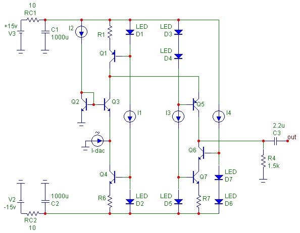
rbroer said:After all suggestions I've come up with a version I'll try next (still enjoying the 1st version though);
I added a PNP cascode on the current conveyor to keep it's Vce pretty constant and as a bonus it creates more Vce voltage headroom on Q5 since it's referenced to negative rail.
I have cascoded current sink Q7 with Q6 since this one will be "seeing" the output voltage swing.
I1 ~ I4 are constant current sources made of jfets with resistor.
I'll be using 2SA970´s & 2SC2240´s
bias Q3, Q5 = 15mA
Vce(Q5) = 19V,
Ve(Q5) = 11V,
Vc(Q5) = -8V (+/-3V signal swing)
Any suggestions for a "bigger" Q5 ?
Questions about the folding-cascode "upgrade" to rbrorer's I/V -- and specifically with respect to its use with TDA1541A:
Are all Q's now 2SA970's & 2SC2240's?
What are the values for R1, R6 and R7 (are these best off as pots)?
Are the LED colors still green ... or will red work better ... or does it really matter?
For anyone who built the orignal and the folding-cascode "upgrade" ... how big of a sonic difference is there between the two?
Thx for any info you can provide.
rbroer said:Built this the last week; it's a variation of Jocko's simple I/V, using all generic unmatched parts, larger bias currents, and the R4 upstream of C3.
This is used in a non-oversampling cd player with Kwak-Clock version 3 and TDA1541A-S1.
I have adjusted Vc(Q3) with pot R6 to 10.0 Vdc
Ve(Q3) is adjusted with pot R3 to 0 Vdc, and readjusted after a few hours. It doesn't change much over time, within +/-1.0mV.
Current source Q1 is about 23mA, of which 6mA flows into R4, 17mA through Q3 and 15mA through current sink Q4.
All bjt's have hfe of ca. 300-400 measured with multimeter.
Since I didn't measure Vbe on Q3 and Q2 I ended up with different R3 values; ca. 5.6k and 22k.
I suppose one could select to get the lowest R3 value, that is, have some moderate current flowing into Q2.
Have fun,
Hello
Did you sim or measure how much distortion this first version of your circuit do have ?
Thank you
Bye
GAetan
Hi Rudolf,Built this the last week; it's a variation of Jocko's simple I/V, using all generic unmatched parts, larger bias currents, and the R4 upstream of C3.
This is used in a non-oversampling cd player with Kwak-Clock version 3 and TDA1541A-S1.
I have adjusted Vc(Q3) with pot R6 to 10.0 Vdc
Ve(Q3) is adjusted with pot R3 to 0 Vdc, and readjusted after a few hours. It doesn't change much over time, within +/-1.0mV.
Current source Q1 is about 23mA, of which 6mA flows into R4, 17mA through Q3 and 15mA through current sink Q4.
All bjt's have hfe of ca. 300-400 measured with multimeter.
Since I didn't measure Vbe on Q3 and Q2 I ended up with different R3 values; ca. 5.6k and 22k.
I suppose one could select to get the lowest R3 value, that is, have some moderate current flowing into Q2.
This circuit can be universally used for other current output DAC's;
use pot R6 to get the wanted Vce on Q3.
To use it with Philips DACs like the TDA1543 and TDA1545A with DC voltage on output, replace Q2 with LED's, zener, or diodes to get stay within the valid DC compliance range.
I do have some SA970's and SC2240's to try, which might sound better...but even with generic parts it sounds pretty good.
Have fun,
Can i substitute 2n3904/6 for the 547/57? Their specs are very similar...
Thanks!
i've built the circuit, and when the volume on the cd is low, it sounds fine. but as soon as samples come above a certain level, they transform to a harsh 'click' or 'pop'. all initial adjustments have been done, but even when seriously offset (try and error-method), the behaviour doesn't change. both channels have the same problem
is hfe very important?
is hfe very important?
hi everybody.
i just bought the last lampucera DAC:
2010 NEW VERSION 24bit/192khz DAC Kit su eBay.it CD Players Recorders, Home Audio, Electronics
who use the opamp, in this case the NE5532, as the I/V conversion stage.
the schematic appear on the first post of this 3D can be used also to replace this type of opamps?
the third opamp you see is for the output and will be replaced by opa627 or audio-gd MOON.
thanks everyone.
rob
ok, then nothing "discrete stage" replacing the opamp.
that will be a big problem.
will come back the opamp rolling.
that will be a big problem.
will come back the opamp rolling.
You need DUAL OpAmps to replace those - 2xOPA627 need to be mounted on a brown-dog adaptor.
Personally I didn't want to complicate thinks. I liked the best the sound of LM4562.
fyi, we were just discussing this DAC's opamps a few topics up on the forum:
New Small DIY Gigawork Dac? - diyAudio
I'm burning-in a Burson module in the output now, the other guy recommends LM4562's in the I/V. Those OPA Sun, Moon and Earth modules pique my interest as well...

ok, then nothing "discrete stage" replacing the opamp.
that will be a big problem.
will come back the opamp rolling.
See the Pass D1 for Sabre thread, thats the only discrete I/V stage I have seen that handles differential output DAC's.
how to increase the output level
Hi powerflux, and anyone who can help
I built the original circuit from rbroer too, but I didn't encounter the problem of click and pop, but I did find out that the output level is low., only 1.1V or so.
Does any one can help me to increase the output level to 2.5~ 3 V??
Any resistors or setup to increase the gain??
I know this is an old thread but since I built so I would like to know how to do further, hope someone can help!!
THX
i've built the circuit, and when the volume on the cd is low, it sounds fine. but as soon as samples come above a certain level, they transform to a harsh 'click' or 'pop'. all initial adjustments have been done, but even when seriously offset (try and error-method), the behaviour doesn't change. both channels have the same problem
is hfe very important?
Hi powerflux, and anyone who can help
I built the original circuit from rbroer too, but I didn't encounter the problem of click and pop, but I did find out that the output level is low., only 1.1V or so.
Does any one can help me to increase the output level to 2.5~ 3 V??
Any resistors or setup to increase the gain??
I know this is an old thread but since I built so I would like to know how to do further, hope someone can help!!
THX
Hi Tubee,
I've built a couple of these recently, and I get the same low output.
As a stopgap, I'm using a simple opamp circuit afterwards, with a gain of about 10.
Seems to bring it up to a more usable level (not that I'm actually measuring anything).
Unless I'm doing anything wrong (I'm using rbroer's first Jocko's IV stage, but doubled the output resistance), I shall begin on a discrete gain stage and buffer.
Phil
I'd really wanted the Simple I/V for TDA1541 (v1 per OP) to work!
I'd had great results with Rudolf's similar I/V for TDA1545A (diyparadise).
Alas, after multiple build attempts, I could not get the I/V to work; I moved onto the similar Jocko I/V and similar no-go.
How many of you reading this have successfully implemented the orig. circuit (v1, see OP) to work?
Refs:
DIYHiFi.org -- I/V and whatever comes after it
- Status
- Not open for further replies.
- Home
- Source & Line
- Digital Line Level
- Simple I/V for TDA1541