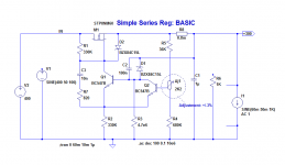
Here are some examples of simple, cheap, medium performance regulators.
They are in the same league as Maida's for example, but are completely discrete.
This means a slightly increased complexity, but also more flexibility and less failure mechanisms.
Key attributes are:
The ripple rejection is shown at 100Hz, for an input voltage of 350V to 450V, first with a load of 10K (30mA), then with no-load, and finally with 1K (300mA)
Next is the output voltage, with a load current varying between 10mA and 110mA, at 1KHz.
And finally, the same in the frequency domain.
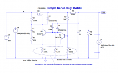
Notes: R8 has no physical existence, its purpose is to indicate the proper layout: R5 placed upstream of D1/output node.
The circuit has been tested with an IRF830
They are in the same league as Maida's for example, but are completely discrete.
This means a slightly increased complexity, but also more flexibility and less failure mechanisms.
Key attributes are:
- Quiescent current <1.5mA
- Low drop-out (limited to the threshold voltage of the pass element)
- Only one high-voltage or power device: the pass element itself
- No minimum or maximum current: they regulate from an open output to a maximum load limited only by the pass element/heatsinking
- Stable, rugged, quiet and tolerant
The ripple rejection is shown at 100Hz, for an input voltage of 350V to 450V, first with a load of 10K (30mA), then with no-load, and finally with 1K (300mA)
Next is the output voltage, with a load current varying between 10mA and 110mA, at 1KHz.
And finally, the same in the frequency domain.
Notes: R8 has no physical existence, its purpose is to indicate the proper layout: R5 placed upstream of D1/output node.
The circuit has been tested with an IRF830
Attachments
Next version uses bypasses to improve rejection/output impedance.
Protection diodes have been added, to improve the survivability in case of unexpected events that may discharge the capacitors into the semi's.
Same pictures as above, plus a variant utilizing a different compensation scheme.
For that one, the performances are somewhat improved, but at the expense of the transient behavior.
Attachments

Finally, any of the previous circuits can be fitted with a current limiter, to improve survivability.
Since in high voltage circuits, the SOAR could easily be exceeded, it will generally be necessary to include a folback mechanism.
Here, R9 determines the current limit, and R11 the amount of folding: for R11=∞, there is no folding, only pure current limit.
R11 cannot be made too small, as the circuit may have difficulties starting up.
If Q3 is in thermal contact with M1, it will also modulate the limit according to the temperature of the pass element, and may act as a thermal shutdown.
The first pic shows the output current at the onset of the limiting, and the second shows what happens when it is exceeded.
Attachments


Elvee, can you make your regulator work at 4 times your voltage? I need a good voltage regulator for GM70 triode, 1200volts... can not find a regulator for those voltages.
There are two aspects to consider here.Elvee, can you make your regulator work at 4 times your voltage? I need a good voltage regulator for GM70 triode, 1200volts... can not find a regulator for those voltages.
One is the input to output differential, and the other is the absolute voltage above ground.
In principle, to regulate high voltages, you don't need high voltage devices: in order to regulate 1200V with a 1225V input, a LM317 would in theory suffice.
In practice, it would be destroyed in a matter of seconds.
Regarding the absolute level of voltage above ground, this regulator is well suited to handle it: there is no voltage-translation circuit from the ground, just resistors, and this makes it very resilient.
To build your regulator, you have basically two options: either you build a circuit that is only capable of handling the input/output differential, with comfortable regulations margins, using a 800V device for example, but then you are not allowed soft-start or current limitation, or anything that requires the MOS to block the full voltage, or you use a 1500V+ device that will allow you the full feature, and will also increase the general ruggedness.
Something like this for example:
http://www.st.com/internet/com/TECHNICAL_RESOURCES/TECHNICAL_LITERATURE/DATASHEET/CD00050744.pdf
Here is the basic regulator adapted for 1200V. A 600V transistor is sufficient, provided you don't have a large decoupling cap to charge at the output.
With a 1500V MOS, it will be more tolerant to mishaps.
But if you really want something bullet-proof, you can turn to glass: the schematic is highly flexible, and can readily be transfered to vacuum, either a power triode or a pentode, see example.
Attachments
Last edited:
Nice. How about soft start too? 🙂
That feature is already included: it is inherent to the bypassed versions, see below the start up sequence:
Attachments
e6 = megohm: 10 to the 6th power.Nice. Would you qoute the value of R2, R3, R4 in post #7.
I forgot to change to a more "civilized" unit.
As I said above, the soft start is implicit in the bypassed versions.How about soft start too?
With the values shown, the time constant is ~0.35s.
This could be increased to any value by increasing C4: with 10µF, it would become 3.5s.
C4 is preferably a film capacitor, or alternatively a high quality E-lytic.
That is necessary because a poor quality, high leakage type would degrade the accuracy of the regulated voltage.
For large values, this could be unpractical, and it would make sense to isolate the starting cap from the regulation loop using diodes.
The following pic shows how this could be done: R8 provides a path for the leakage currents, and D5 isolates C5 from the regulator once the start up period is over.
C5 can thus be any standard quality E-cap.
Note that this variant has not been actually tested, but it should work without too many surprises
Attachments

Last edited:
Hi,
Sorry for digging up old topic, but I wonder how can I adjust the output voltage?
Thanks,
Duong
Sorry for digging up old topic, but I wonder how can I adjust the output voltage?
Thanks,
Duong
No problem.Hi,
Sorry for digging up old topic, but I wonder how can I adjust the output voltage?
Two cases here:
-You want to keep the 300V output, but make it adjustable by a small amount:
Insert a trimmer in the feedback divider, R4, R5.
-You want to actually modify the output voltage, from say 300 to 400V: you multiply the value of the three bottom resistors by 400/300=1.333
In addition, R1 may need to be modified too, depending on the input voltage: the current through this resistor with the max In-Out differential must not exceed the current through R2, otherwise the regulation will be lost
Attachments
No problem.
Two cases here:
-You want to keep the 300V output, but make it adjustable by a small amount:
Insert a trimmer in the feedback divider, R4, R5.
-You want to actually modify the output voltage, from say 300 to 400V: you multiply the value of the three bottom resistors by 400/300=1.333
In addition, R1 may need to be modified too, depending on the input voltage: the current through this resistor with the max In-Out differential must not exceed the current through R2, otherwise the regulation will be lost
Such great help, thanks!
I'm planning to build 2 separated/isolated units of regulated 350VDC to stack on my Kikusui variable 350VDC/0.2A PSU to make my experiment 1000VDC. Is there anything else I need to pay attention to?
Rgrd,
Duong
In this case, I recommend you use the protected version: http://www.diyaudio.com/forums/power-supplies/198986-simple-hv-series-regulators.html#post2753591 and you add an anti-reversal diode in parallel with the output.Such great help, thanks!
I'm planning to build 2 separated/isolated units of regulated 350VDC to stack on my Kikusui variable 350VDC/0.2A PSU to make my experiment 1000VDC. Is there anything else I need to pay attention to?
Your Kikusui should already have one, but make sure it is actually present.
Also, make sure your parts, transformers in particular have a sufficient circuit to chassis insulation: 1kV in this case
It's a rather cool design. A pair of questions if I may ?
- would the irfbc40 suitable ? It's a 6A/600V mosfet but input capacitance is quite a bit higher. Otherwise, I've irf710 on hand.
- would it be a good idea to add a gate stopper to the mosfet ?
- how critical is the output capacitor for stability ? Should it be low esr or rather not, very close to the output or not ?
Thank you 🙂
I think so: a STW11NM80 sims alright, and its capacitance is 2nF- would the irfbc40 suitable ? It's a 6A/600V mosfet but input capacitance is quite a bit higher.
The IRF710 works, it has been tested in realityOtherwise, I've irf710 on hand.
It doesn't seem to cause problems in sim, but I'd be cautious: in an actual circuit, the additional pole thus created might have unexpected effects. You can test it, but stay on your guard- would it be a good idea to add a gate stopper to the mosfet ?
The circuit will be stable even with a very low esr type, like foil PP, but as with most closed loop systems, it will be more stable if the cap has some series resistance, between 0.1 and 1 ohm.- how critical is the output capacitor for stability ? Should it be low esr or not?
If you want an exceptionally stable circuit, you can add a series RC 1µ/0.47 ohm in parallel with the output capacitor.
The circuit is also stable without any capacitor, but the output impedance will rise with frequency
Ok, thank you. I needed a new 300V-80ma regulator for an headphones amplifier and this is better, cheaper and easier than what I was using before (this from Tubecad), especially it doesn't need any HV transistors.
Considering your remarks, I'll try with the irfbc40, no gate stopper and 1uF/0R5 at the output. There will be two 20uF mkp caps near the amplifiers pcb.
Can be made quite small too. Layout below is 7/5cm.
Considering your remarks, I'll try with the irfbc40, no gate stopper and 1uF/0R5 at the output. There will be two 20uF mkp caps near the amplifiers pcb.
Can be made quite small too. Layout below is 7/5cm.
Attachments

- Status
- Not open for further replies.
- Home
- Amplifiers
- Power Supplies
- Simple HV series regulators