Hi,
I would like to use a simple high voltage regulator for a SE project.
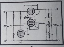
I came out with this preliminary schematic, where the feedback of the output ripple to the gate of the main mosfet (M1) is given by a mosfet (M3) loaded with CCS (M1) to maximize its gain so its correction (idea taken from @SpreadSpectrum Corona amp, where he loads a pentode by a CCS to maximize its gain and apply more nfb).

On simulations, supplying 100 mA with a 20Vpp ripple at infeed I get 600 uVpp ripple at its output, that is a 90dB reduction.
It seems too optimistic, so... what am I overlooking?
I know all safety measures for turn on/off are missing, but that will be checked and then asked later on.
Thanks in advance
I would like to use a simple high voltage regulator for a SE project.
I came out with this preliminary schematic, where the feedback of the output ripple to the gate of the main mosfet (M1) is given by a mosfet (M3) loaded with CCS (M1) to maximize its gain so its correction (idea taken from @SpreadSpectrum Corona amp, where he loads a pentode by a CCS to maximize its gain and apply more nfb).
On simulations, supplying 100 mA with a 20Vpp ripple at infeed I get 600 uVpp ripple at its output, that is a 90dB reduction.
It seems too optimistic, so... what am I overlooking?
I know all safety measures for turn on/off are missing, but that will be checked and then asked later on.
Thanks in advance
90dB reduction at 50Hz is not unusual.
What you really should check is the output impedance under varying load, because that determines the supply ripple due to audio signal load.
Make a current source loading the output, say 50mA rms, and do a .ac with it from 20Hz to 20kHz, and look at the signal that this produces at the output.
For instance, if you see 10mV signal at the output when loaded by 50mA rms, that is an output impedance of 10mV/50mA = 0.2ohms.
Good supplies have Zout in the double-digit milliohms, at least at mid frequencies.
Jan

Why should you want such low output resistance?
In the end, it will be nothing compared to internal resistance of the tube, regardless of how simple or complicated the regulator is.
In the end, it will be nothing compared to internal resistance of the tube, regardless of how simple or complicated the regulator is.
I'd be interested in something simple on a PCB. The Salas is popular - what's the link to that PCB?
I think Allen Wright did something?
I think Allen Wright did something?
There is no relation to the tube internal resistance.Why should you want such low output resistance?
In the end, it will be nothing compared to internal resistance of the tube, regardless of how simple or complicated the regulator is.
It is important because regulator output impedance determines the signal related ripple on the supply output, caused by the varying current the supply must deliver.
That ripple will never be a nice sine wave, it is distorted and has loads of harmonics.
Since those harmonics on the supply appear at the output, attenuated by the amplifier ripple rejection parameter, it has a large impact on the amplifier performance. Especially single ended tube amps have very low ripple rejection, sometimes none at all, meaning supply ripple appears at the output at full blast.
As an example, if you output 10Vrms and there is a ripple from the supply on the output of 100mV, that's 1% distortion even with a perfect amplifer.
And that is audible and not nice.
Jan
The question is how much you're looking for?
Because for just an audio amplifier I wouldn't go that far personally.
Just a simple capacitance multiplier will work fine.
At least HEAPS better compared to a massive choke filter.
Anyway, if you want to take a step further, I think it's hard to beat a LM317 with a cascaded MOSFET or NPN in front.
To keep voltage difference low enough for the LM317.
Since a LM317 is a floating regulator, you can technically do without, but you only need one tiny mistake or other "blib" and it will be totally be fried obviously
"Because for just an audio amplifier I wouldn't go that far personally.
Just a simple capacitance multiplier will work fine.
At least HEAPS better compared to a massive choke filter."
Could you post some links? Never used a capacitance multiplier. This would be for around 320V
Just a simple capacitance multiplier will work fine.
At least HEAPS better compared to a massive choke filter."
Could you post some links? Never used a capacitance multiplier. This would be for around 320V
100mV ripple is a lot even if you don't use an regulator.
Still I do not understand what ripple has to do with miliohms output impedance.
Could you please make it clear to me.
Still I do not understand what ripple has to do with miliohms output impedance.
Could you please make it clear to me.
Last edited:
I suggest to replace M3 with a double gate MOS transistor, and feed G2 with a sample of input voltage. This correct output voltage before it is present at the output. This idea is not mine, it is dated to middle of past century where pentodes or two triodes cascoded were used as voltage amplifiers and screen suply was taken from input. More data can bw found in the web and in google patents. I may suggest some by PM.
Attachments
"The big issue that we may end up with is the heat dissipation depending on the load we are planning to use this circuit. You may end up wasting too much heat and requiring a big heatsink for the pass MOSFET, hence this circuit isn’t practical for an amplifier. I don’t recommend using it for an amp, you have been warned! "
I'd be using it for 320V at 140mA......
https://www.bartola.co.uk/valves/2024/04/12/cap-multiplier-pcb-build-guide-and-bom/#more-11714Update
@andyjevans That's the one I would go for
Here a more technical explanation;
https://audioxpress.com/article/the-capacitance-multiplier
Use one of those isolated variants, so you can just mount it directly to the chassis.
That advice is completely without any context and making people scared and assume things for no good reason.The big issue that we may end up with is the heat dissipation depending on the load we are planning to use this circuit. You may end up wasting too much heat and requiring a big heatsink for the pass MOSFET, hence this circuit isn’t practical for an amplifier. I don’t recommend using it for an amp, you have been warned! "
Let's assume a 10V voltage drop across the MOSFET, 320V output @ 140mA
Power dissipation across the Mosfet is; P=Vdrop*I = 10*0.14 = 1.4W
Which is not that insane.
May I ask what kind of SE amp this is @andyjevans ?
Because 140mA is rather high for a SE amp?
Or is that two channels?
In that case you could use a MOSFET per channel to split it into 0.7W each.
In practice the voltage drop can be a little lower, depending on the MOSFET, but 5-7V is perfectly doable.
With a transistor we have to use a Darlington pair, in that case we can go down to about 1.6V or so.
In my experience MOSFETs just work a little easier
You can use heatsinks as amplifier's lateral walls. Royal choice, you can drop even 70V on regulators and use as many as you wish.
https://modushop.biz/site/index.php...t_id=920&search=Heatsink+250&description=true
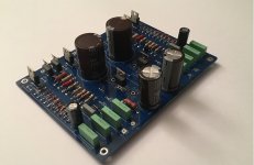
Here is what I will use for my new 845 amplifier
Here is what I will use for my new 845 amplifier
Those are content free comments.Just a simple capacitance multiplier will work fine.
At least HEAPS better compared to a massive choke filter.
Is 'working fine' a goal for this circuit?
Can you define HEAPS? 10 times,? 5.66 times? Worse actually?
Jan
While that is of concern, I am going to be doing just that. A very highly knowledgeable member here is designing the regulated PS system. The semiconductors that can handle the load in DC operation do exist and when compared to tube rectification drop, the $$$ chokes and the inefficiency and unreliablilty that go with that I am pretty convinced SS PS will come out on top."The big issue that we may end up with is the heat dissipation depending on the load we are planning to use this circuit. You may end up wasting too much heat and requiring a big heatsink for the pass MOSFET, hence this circuit isn’t practical for an amplifier. I don’t recommend using it for an amp, you have been warned! "
I'd be using it for 320V at 140mA......
My only concern is the input capacitance of big powerful mosfets and possible sonic impact. Ale Moglia recommends a low input cap to 220 pass mosfet for preamp but that will fail in short order at ~200-300mA.
I was just testing Ale cap multiplier last night with that to220 plastic mosfet at 30mA-15kohm load with a puny heatsink dropping about 90V it was getting hot but still touchable. The preamp will require ~60mA so I am going to revise the CRC value to where I will drop ~50-60V during reg. With an actual heatsink the whole thing should work great.
Well there are millions and millions of people using all kinds of high-end amplifiers without ANY kind of regulation and they seem to be extremely happy with it.Is 'working fine' a goal for this circuit?
Getting a PSRR of around roughly 50 to 65dB is perfectly doable.
With a load regulation of about 0.1-0.2% worst case or so.
They are a lot easier, smaller and cheaper than a massive filter choke.
So what's the point of discussing it exactly?
I am most certainly not gonna do it, these circuits are so super basic.
I find that extremely pedantic, capacitance multipliers have been around for an extremely long time.
There is an absolute plethora of information about them, but from people with certain background I expect they already know all these ins- and outs as well as the advantages and disadvantages.
If you have doubts, and don't want to read, fire up your favorite SPICE simulator and simulate a nice little circuit within 5-10 minutes.
That's less work than going into yet another never ending discussion that goes nowhere and loosing any grip of the bigger picture.
If you think that a very high amount of PSRR is mandatory, this is obviously not gonna work.
But that was already obvious straight from the beginning.
But if you're going that far, I doubt if a tube amplifier is even gonna be the right starting point to begin with.
Unless you REALLY know what you're doing and also designing the rest of the circuit accordingly.
I use this circuit for years, it works fine with a good range of voltages and current.
It is dual channel; it is possible to use the ss diodes or a tube rectifier ( a pad directly from it)
I tested it with a range of current from 20mA to 300mA with a very good stabilization and the ripple is almost zero volt.
The schematic is one channel
It is dual channel; it is possible to use the ss diodes or a tube rectifier ( a pad directly from it)
I tested it with a range of current from 20mA to 300mA with a very good stabilization and the ripple is almost zero volt.
The schematic is one channel
Attachments
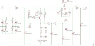
Nice schematic, voltage regulator combined with a capacitance multiplier. I am using something similar in my current projectI use this circuit for years, it works fine with a good range of voltages and current.
It is dual channel; it is possible to use the ss diodes or a tube rectifier ( a pad directly from it)
I tested it with a range of current from 20mA to 300mA with a very good stabilization and the ripple is almost zero volt.
The schematic is one channel
- Home
- Amplifiers
- Tubes / Valves
- Simple high voltage regulator suggestions