Hi!
I'll post you my thoughts.
Usually telephone amplifier is built according to this wiring diagram:

http://s41.radikal.ru/i093/1606/e8/a6591b404ffb.gif
Voltage gain gives operational amplifier with Ku about 60 dB at 20 kHz, so there is little depth NFB, less Ku operational amplifier to a dozen decibels. How to improve this amplifier? To use Op-Amp with a wider bandwidth. Such wideband Op-Amp is prone to generate.
But there is another method.

http://s016.radikal.ru/i336/1606/d9/aef34601d10d.gif
Add a one or couple of transistors and get the depth of the NFB of more than 150 dB, and more then 80 dB at 20 kHz.
But it can not work well? 😱
Can. And work. 🙂
Op-Amp works in this scheme the small-signal regime: its AC output voltage is about 5 mV. Therefore it has no distortion. He just doesn't know that he amplifies the signal. 🙂

http://s019.radikal.ru/i611/1606/06/ed98ca798593.png

http://s020.radikal.ru/i723/1606/2e/827c060b0539.jpg

http://s017.radikal.ru/i406/1606/84/5708e6966aca.jpg

2 V, 32 Ohm.
http://s017.radikal.ru/i433/1606/6e/1e690f98bb90.jpg

http://s50.radikal.ru/i128/1606/79/27c4b8ec0dc1.jpg

http://s12.radikal.ru/i185/1606/82/fa27f8b68c57.jpg

http://s019.radikal.ru/i616/1606/2a/c92056f52d0f.jpg
The picture of the PCB attached. You can order the PCB industrial manufacture here: aleanu@gmail.com.
Attachments
Last edited:
You are still in doubt. 🙂
1. First, it is simple and it can be done in one evening 🙂. For example, this amplifier contains 10 transistors + single Opamp average quality. Brand amplifier The β22 stereo amplifier

has 26 transistors and is much more complicated.
2. The small size of the amplifier allow you to incorporate it into any design. The Board is designed for mounting on the metal wall of the pre-amplifier.
3. Easier adjustment. Matched pairs of transistors is not needed. Only need to adjust the idle current.
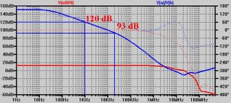
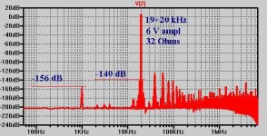
4. At the same time the amplifier has high parameters. The depth of the NFB for different variants of the amplifier changes from 150...120 dB to 1 kHz, and to 93 dB for 20 kHz, Fig. 1. This is enough to get ultra-high linearity, Fig. 2. Such linearity is not available for many of the other amps built by other circuitry. With this amplifier can compete on quality only "composite" Opamp + Opamp.
You can verify this yourself on the model.
1. First, it is simple and it can be done in one evening 🙂. For example, this amplifier contains 10 transistors + single Opamp average quality. Brand amplifier The β22 stereo amplifier
has 26 transistors and is much more complicated.
2. The small size of the amplifier allow you to incorporate it into any design. The Board is designed for mounting on the metal wall of the pre-amplifier.
3. Easier adjustment. Matched pairs of transistors is not needed. Only need to adjust the idle current.
4. At the same time the amplifier has high parameters. The depth of the NFB for different variants of the amplifier changes from 150...120 dB to 1 kHz, and to 93 dB for 20 kHz, Fig. 1. This is enough to get ultra-high linearity, Fig. 2. Such linearity is not available for many of the other amps built by other circuitry. With this amplifier can compete on quality only "composite" Opamp + Opamp.
You can verify this yourself on the model.
Attachments
Last edited:
Other than being much simpler to construct and using a op-amp, in what ways does this amp differ from the "ultra high resolution" amp in your other thread?
Which amp actually sounds better?
Measurements are nice, but in the end it's all about the sound quality for me.
Also, thank you for posting the Sprint file for the PCB. Someone did a very nice job laying it out.
Which amp actually sounds better?
Measurements are nice, but in the end it's all about the sound quality for me.
Also, thank you for posting the Sprint file for the PCB. Someone did a very nice job laying it out.
I built this amp a few years earlier, than UNICUM. It is designed for integration into my existing preamp industrial manufacturing.Other than being much simpler to construct and using a op-amp, in what ways does this amp differ from the "ultra high resolution" amp in your other thread?
Which amp actually sounds better?
The story of UNICUM is that I invented it, developing a powerful amplifier. And posted on the Internet, but I didn't build it. UNICUM has built a different person, he lives at a distance of 600 km from me. He spent all the necessary measurements and give for UNICUM a high rating.
After that UNICUM was built by one man working ... a sound engineer. 🙂 He argues that the amplifier does not make the signal any unnecessary artifacts. That's exactly what he said: on any headphones (and they have a very expensive professional headphones) is not audible artifacts. And this engineer earns this amplifier is in secret from his boss. That, frankly, is a privilege for me.

These two amp have never been compared in sound. I think their sound will be identical. After all that, and the other distortion is close to the noise floor, and less than the distortion of CD-recordings. Therefore, I can not help you in choosing the best of them. Good one and the other.
The only difference is that the UNICUM was developed in the framework of the concept of "short sound path": "source-volume control-amp" and therefore can work with sources with high output impedance without distortion. The discussed amplifier is designed only to work from sources with a low output impedance.
In the near future I plan on posting here for another amp, a little more complicated than UNICUM. This amplifier is now undergoing a series of measurements and listening at home my friend.
In these things I agree with Douglas Self's, that said: "If the (measured) no distortion, no one will hear. There is nothing to hear", or something like that. Then we can look for reasons why this or that sound in other places.Measurements are nice, but in the end it's all about the sound quality for me.
Thank you. I was drawing this. Of course, it would be smaller jumpers. 🙂Also, thank you for posting the Sprint file for the PCB. Someone did a very nice job laying it out.
Last edited:
I have some boards coming from Mr. Alexandr for the UNICUM. I will try to get it assembled and working before trying any other amplifier.
So you actually designed both the UNICUM and this simple headphone circuit?
What is the gain of the simple headphone amp?
Thanks...
So you actually designed both the UNICUM and this simple headphone circuit?
What is the gain of the simple headphone amp?
Thanks...
It would be good then to compare their sound. Also it would be nice to measure distortion with the sound card.I have some boards coming from Mr. Alexandr for the UNICUM. I will try to get it assembled and working before trying any other amplifier.
Yes, I designed these amps. For example, a simple amplifier is a simplified version of this powerful amplifier, whose scheme laid out in this thread.So you actually designed both the UNICUM and this simple headphone circuit?
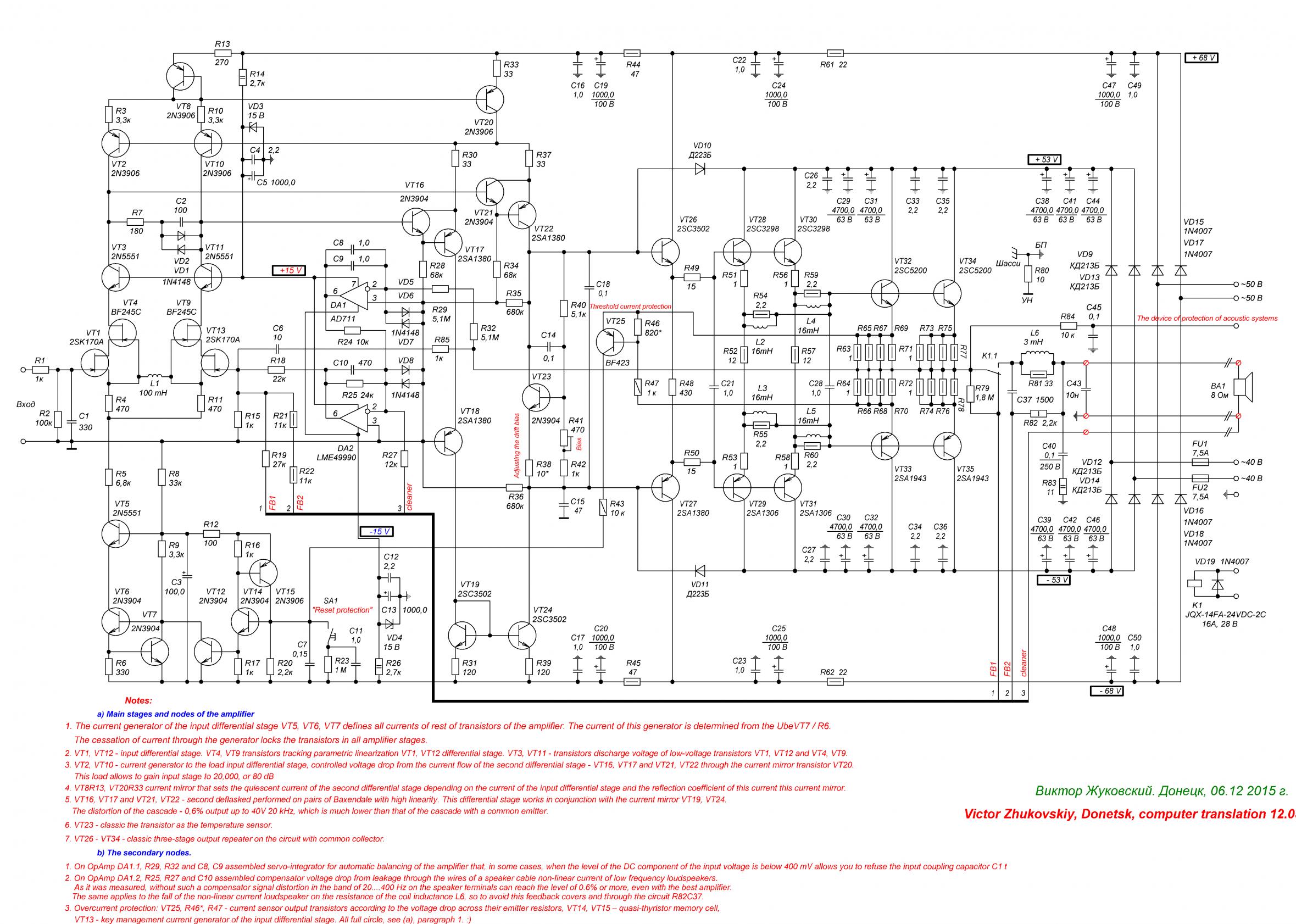
The first version of this amplifier was so done, see diagram at the bottom of the post. We see, that if we exclude from the scheme VT2, which is not needed when the power supply 2x15 V, and to reverse the polarity of VT1 on NPN, that the signal received at the emitter VT5, it turns out the scheme is simple headphone amplifier. UNICUM - this is a step on the way to the amp CRAFTSMAN. I promised to create a topic about a new amplifier: this new amplifier circuit design is very similar to CRAFTSMAN, but easier. It has no overcurrent protection (VT12,VT14,VT15,VT25), unit resistance compensation cable (DA2), simpler output stage.
G=(R6+R5)/R5=4,3.What is the gain of the simple headphone amp?
Attachments
Last edited:

I'm talking about, how to build amplifier, that you could be proud of. 🙂 And that's all. 🙂can someone tell me what the hell this diatribe is about? Apart from pop ups that is!
Hi all!
Amazing thing. A lot of people bought the kits to build these amplifiers http://www.diyaudio.com/forums/headphone-systems/292669-ultra-hi-res-headamp.html http://www.diyaudio.com/forums/headphone-systems/292834-simple-head-amp-high-linearity.html, some people bought them along with the boards of the DC protection on the output. But nobody is giving me feedback about their experiences. Neither bad nor good. However, do not return and do not complain.
Amazing thing. A lot of people bought the kits to build these amplifiers http://www.diyaudio.com/forums/headphone-systems/292669-ultra-hi-res-headamp.html http://www.diyaudio.com/forums/headphone-systems/292834-simple-head-amp-high-linearity.html, some people bought them along with the boards of the DC protection on the output. But nobody is giving me feedback about their experiences. Neither bad nor good. However, do not return and do not complain.
When I get one channel of the Hi-Res headamp completed and working, I'll be glad to give you some feedback compared to the much easier-to-build JLH clone amp.
The Hi-Res amp has many components. Locating some of the components has been somewhat of a challenge for me to say the least.
When locating some of the larger TO-126 transistors, you have to be careful with all the Chinese fakes out there.
Most of these CRT driver transistors have been discontinued for years.
I would change the schematic in the first post as your schematic as it has nothing in common with the one Alexandr provides with boards other than capacitor and resistor values being the same. It is misleading and confusing if someone tries to go by it when assembling the boards.
All of the transistors are different except the 2SK170 & BF245C JFETs.
I wasted quite a bit of money on 2SA1175/C2785 transistors when the boards are designed for BC547/557.
Also, the board is laid out for 3.5mm LS for the 1,000uF capacitors. Good luck trying to find 1KuF caps with only 3.5mm LS! Almost all good caps I found that size are 5mm LS.
When I asked Alexandr why he used 3.5mm LS on the boards, he replied that you originally had only 47uF caps in those locations.
One thing I can say with certainty...Alexandr has been very helpful and prompt in answering all my questions as well as selling me matched input transistors for a reasonable price.🙂
Hi!
Thanks for the reply!
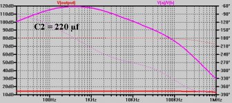
You can assemble this head-amp with C2 47.0 µf , 100.0 UF, 220.0 µf or 470.0 µf, and it will not be wrong, will not lead to the loss of sound quality - as you can see in the image frequency response, the depth of the NFB still remain 88 dB at 16 Hz, at 47.0 µf, 100 dB at C2 220.0 µf, and 107 dB at 470/0 µf.
For Phono preamp required C2 1000,0 uf and more.
Thanks again for your opinion. This will help me to make the amplifier if not better, clearer. 🙂
Thanks for the reply!
We ourselves suffer from it, same as you.When locating some of the larger TO-126 transistors, you have to be careful with all the Chinese fakes out there.
Yes, you are right that these transistors are not available. To build a powerful amplifier to stock up on these transistors. For example, there is the old Soviet КТ940В(npn) and КТ9115А(pnp), well they replaced 2SC3502/2SA1380 and the like. But here, in this amplifier, these transistors cannot be used. These high voltage transistors are Hfe decrease and increase of base current at voltages collector-base (collector-emitter) of less than 7...8 V. This leads to signal distortions when amplitude the output voltage of the amplifier is greater than 10 volts. In this amplifier it is possible to use transistors with only low Vceo, about 60...80 V. They are not prone to this effect. The output will fit any vintage transistors, like BD139/BD140.Most of these CRT driver transistors have been discontinued for years.
You could specify a sequence number for these parts? Elements R5 and C4 connected in series, so they can be rearranged, swapping, and it does not lead to critical errors. The amplifier is working, its parameters will remain the same.I would change the schematic in the first post as your schematic as it has nothing in common with the one Alexandr provides with boards other than capacitor and resistor values being the same. It is misleading and confusing if someone tries to go by it when assembling the boards.
This capacitor C2 happened interesting story. Based on the circuitry of this amplifier I decided to create a Phono preamp. Capacity depth 47.0 µf NFB is more than enough to get high parameters for head amplifier with its amplification 2 times. Phono preamp needs to develop at low frequencies a much greater gain, and capacitor 47.0 µf was not enough to obtain the desired depth of NFB.Also, the board is laid out for 3.5mm LS for the 1,000uF capacitors. Good luck trying to find 1KuF caps with only 3.5mm LS! Almost all good caps I found that size are 5mm LS.
When I asked Alexandr why he used 3.5mm LS on the boards, he replied that you originally had only 47uF caps in those locations.
You can assemble this head-amp with C2 47.0 µf , 100.0 UF, 220.0 µf or 470.0 µf, and it will not be wrong, will not lead to the loss of sound quality - as you can see in the image frequency response, the depth of the NFB still remain 88 dB at 16 Hz, at 47.0 µf, 100 dB at C2 220.0 µf, and 107 dB at 470/0 µf.
For Phono preamp required C2 1000,0 uf and more.
Thanks again for your opinion. This will help me to make the amplifier if not better, clearer. 🙂
Attachments
I can't boast of anything. Two gain stages give the NFB a depth of 80...95 dB at 20 kHz to 120...140 dB in the lower frequencies. 🙂 That's all. 🙂
Attachments

Last edited:

- Status
- Not open for further replies.
- Home
- Amplifiers
- Headphone Systems
- Simple head-amp with high linearity