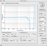
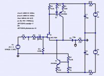
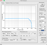
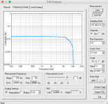
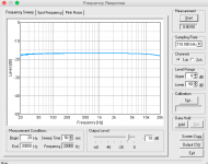
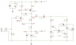
Specs here are:
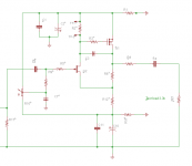
Simple enough to fab point to point, no ICs what so ever, works with any semiconductor, programmable gain, low 0db input distortion and lots of headroom.
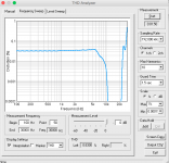
Plots shown are with 7.5dB gain.
The overall personality is of course set with bias pot. You can go for 0.04%thd symmetrical clipping 18v or more PP output, lowest thd for hi-fi, or anything in between.
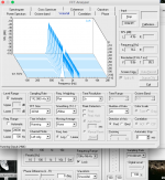
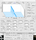
Typical THD is .01-.02% no global FB. No 5ths observed.
The circuit does not model correctly with any version of Spice unless empirically tweaked.
Test load for plots is 3.3k, simulating a low-z tone stack.
The real beauty of old 60's Sziklai CFP is it is amazingly indifference to semiconductors used. I have mixed Soviet Germanium with modern mosfets etc.
Bruce
Attachments
Member
Joined 2009
Paid Member
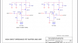
Hi, I think I probably don't understand the schematic symbols for "ground" and for "positive supply". Does R11 connect to the positive supply? If so then I don't see any pathway that allows DC current to flow from the drain of Q2, to ground.
It's surprising that (a) the real-life physical circuit is so robust that it works well with any semiconductors at all; yet (b) it does not work correctly in circuit simulation. I haven't heard that before.
It's surprising that (a) the real-life physical circuit is so robust that it works well with any semiconductors at all; yet (b) it does not work correctly in circuit simulation. I haven't heard that before.
R1 is connected to -15V, R10 to +15V .
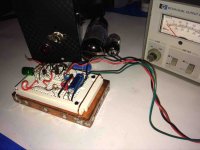
That is my test 6l6-12ax7 SE test amp in background.
I'm doing audience testing with it but ultimately moving to JLH type output.
That is my test 6l6-12ax7 SE test amp in background.
I'm doing audience testing with it but ultimately moving to JLH type output.
Sorry for the off-topic question, but what programs are you using to test THD? Are they measuring THD off a simulation or the physical amp pictured? I find that I am now in need of some tools (THD analyzer, oscilloscope, etc.), but do not have the room to store them (never mind the high prices) , so it would be nice if there was a decent computer-based solution.
its a stienburg ur22 interface to macbook then software(s) Thd fft etc.
Verify with other software then a Leader LDM-170 , HP 331A for reality check.
I use several sw packages. the one shown is a demo from Yoshimasa Electric , can send the link if you're interested. i use a wine like platform for windows on osx.
yes those measurements fron that circuit pictured. no sim.
I gave away my Tektronix 465b and now just use a fluke 97 for the same reason space available
standing on shoulders of others
Here is an Italian work called MiniMaLast.
http://www.tecnotre.it/audio/elettroniche/minimalast/SCHEMA-MML-03-2014.pdf
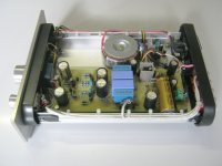
Pic here of a completed.
And David Johnsons, I cant find link so attached here pic.
This is all a lot of fun , I'm going back to my feral technician state of dumpster diving for transistors.
it's a challenge to build high-quality fi with few components ,no integrated circuits etc. so that's the kick.
I did some audience testing with tone stacks and the "tilt" definitely wins.
So on to finals.
Attachments
Contrary to expectations, a buffer with high input impedance very badly interact with the signal sources with a large output resistance - that is, in those applications where these buffers and need.
For example, will gather in LTspice IV, a simple model of the buffer with a resistor R2 40 k.This resistor simulates the output resistance of the signal source V1. While this resistor shorted and output impedance V1 is 1 k, THD is 0.006%. As soon as the output impedance becomes equal to 40 kilo Ohm, the THD goes up... to 0.16%.
And, of course, this situation has several outputs.
Attachments
bias
Yes, one of the issues I saw with LTspice (or any) simulation is inaccuracy of THD calculations.
For example I did a reality check by running a series of measured THD tests with an external series 1K resistor to input , and then a series 1M to input. The expected 1-2 db voltage drop was of course seen due to division by R17 and R9. The THD was unchanged. I also did a response plot with the 1M series input.
My goal is 2M input z.
I think the problem with sim here is the bias adj R10 effects are very difficult to model. I gave up on fixed bias a long time ago. THD will always be higher with fixed bias. (unless tweeked)
Attached are the circuit values and two plots showing effects of different bias settings. One file is R10 adjusted for min THD at 5khz other at 10khz. Input is -6db.
Very low THD results can be obtained by adjusting bias at one single frequency. i.e. 1khz.
My plots do seem to match your THD sim on the low end at .0000xx.
I have some ideas on why the Sziklai/Lin/JLH CFP excel but that will be in a later post.
Attachments
Contrary to expectations, a buffer with high input impedance very badly interact with the signal sources with a large output resistance - that is, in those applications where these buffers and need.
For example, will gather in LTspice IV, a simple model of the buffer with a resistor R2 40 k.This resistor simulates the output resistance of the signal source V1. While this resistor shorted and output impedance V1 is 1 k, THD is 0.006%. As soon as the output impedance becomes equal to 40 kilo Ohm, the THD goes up... to 0.16%.
And, of course, this situation has several outputs.
This is simply not true.
Input impedance of the jFET at 1 KHz (taking in account its input capacitance) is around 27 Mohm. So, output impedance of the previous cascade in the order of 1 Kohm, or 41 Kohm, or 100 Kohm does not really influence the buffer's distortion level.
You can have R3 = 100 Kohm, or 220 Kohm, or 2 Mohm = distortion will be the same, only the output level will be slightly different because of attenuation effect at the input.
If your model shows otherwise - there's something wrong with your model.
Maybe, maybe... Give your, more correct, model, without distortion, provided the large output resistance of the signal source. 😎This is simply not true.
Input impedance of the jFET at 1 KHz (taking in account its input capacitance) is around 27 Mohm. So, output impedance of the previous cascade in the order of 1 Kohm, or 41 Kohm, or 100 Kohm does not really influence the buffer's distortion level.
You can have R3 = 100 Kohm, or 220 Kohm, or 2 Mohm = distortion will be the same, only the output level will be slightly different because of attenuation effect at the input.
If your model shows otherwise - there's something wrong with your model.
 🙂
🙂 I'm afraid you won't find it. In such circumstances, almost all amplifiers introduce very large distortions, with the exception of specially develop to reduce this problem. 🙂
Last edited:
Maybe, maybe... Give your, more correct, model, without distortion, provided the large output resistance of the signal source. 😎🙂
I'm afraid you won't find it. In such circumstances, almost all amplifiers introduce very large distortions, with the exception of specially develop to reduce this problem. 🙂
Here we go...
Attachments
Why not keep it simple ?
Mona
Need headroom more headroom more headroom....but i'm going to try your suggestion. 🙂
I used numerous P-channel types and can you believe J174 works great?
The utmost important is bias set. You can change the intended product sound with adj. It will keep production engineer from complaining too.
R2 is tweaked once for a batch of jfets/mosfets. Proto is around 14k.
I choose not to put input gate protection based on experience with ESD CE testing. It is better for the part to completely fail rather than be damaged but quasi-working.
Unknown file format. Show the schema graphically, and then specify how you have achieved circuit design the lack of distortion in high-output resistance.Here we go...
Last edited:
Unknown file format. Show the schema graphically, and then specify how you have achieved circuit design the lack of distortion in high-output resistance.
It's exactly the same as your schematic in post #8, but Multisim format and having k117 jFET at the input.
So, what is the mechanism of the problem? Why, in your opinion, distortion increases with the source's output impedance increase?
Yes headroom, with the J174 my idea doesn't work, Vgs of 5...10V leaves no headroomNeed headroom more headroom more headroom....but i'm going to try your suggestion. 🙂
I used numerous P-channel types and can you believe J174 works great?
The utmost important is bias set. You can change the intended product sound with adj. It will keep production engineer from complaining too.
R2 is tweaked once for a batch of jfets/mosfets. Proto is around 14k.
I choose not to put input gate protection based on experience with ESD CE testing. It is better for the part to completely fail rather than be damaged but quasi-working.
 .
.With 14k and the capacitance there (Miller & co) I suspect you dont get much high frequencies out.
Mona
Contrary to expectations, a buffer with high input impedance very badly interact with the signal sources with a large output resistance - that is, in those applications where these buffers and need.
For example, will gather in LTspice IV, a simple model of the buffer with a resistor R2 40 k.This resistor simulates the output resistance of the signal source V1. While this resistor shorted and output impedance V1 is 1 k, THD is 0.006%. As soon as the output impedance becomes equal to 40 kilo Ohm, the THD goes up... to 0.16%.
And, of course, this situation has several outputs.
Want to make sure i understand , you are saying the source z effects output THD?
?
Yes headroom, with the J174 my idea doesn't work, Vgs of 5...10V leaves no headroom.
With 14k and the capacitance there (Miller & co) I suspect you dont get much high frequencies out.
Mona
Look at the response plot. It does fall off above 20khz.
Square wave is nice until 20+khz.
Using low pf gate on the n channel part goes nicely to 100khz+.
But the goal is using generic widely available parts.
A Si or Ge bjt works good too.
-
Yes, it is.Want to make sure i understand , you are saying the source z effects output THD?
?
This is evident in practical measurements and the model.
- Status
- Not open for further replies.
- Home
- Amplifiers
- Solid State
- Simple discrete Sziklai pre
