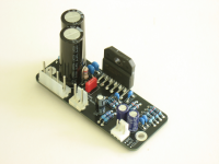
My first gainclone build was built on BrianGT's compact (2.9×1.2inch, 75x30mm) boards. While these days I like larger boards for my builds, I've always liked the challenge of fitting better performance in this small form factor.
So here it is again, this time, with a balanced input and even lower distortion and better sound, using "normal" size (i.e. D=2.5mm L=7mm) axial resistors instead of compact ones.
I am posting some pictures for now and will update this thread in the coming days.
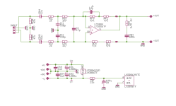
Schematic:
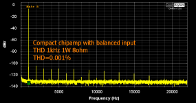
THD 1kHz 1W 8ohm (0.0010%):
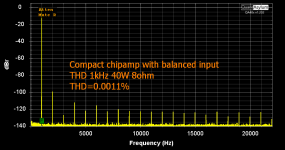
THD 1kHz 40W 8ohm (0.0011%):
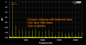
THD 1kHz 70W 4ohm (0.0029%):
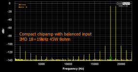
IMD 18+19kHz 1:1 45W 8ohm:
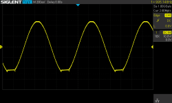
Clip 1kHz 4ohm with +/-28V power supply rails:
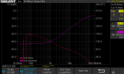
CMRR (1% resistors, balanced source):
Last edited:
Just ground negative inputMake an unbalanced version, too.
Nice Alex,
It is in my pipeline to do almost exactly the same, with single LM3886 for surround and general amp for easy load, and one with 3 x in parallel for 4 ohm sonus fabers with notorious load.
Couple of suggestions, out of guts not simulation:
Here was nice thread discussing this, even if thread wondered back and forward off subject... https://www.diyaudio.com/community/...tempt-this-time-4-of-them.410291/post-7626962
It is in my pipeline to do almost exactly the same, with single LM3886 for surround and general amp for easy load, and one with 3 x in parallel for 4 ohm sonus fabers with notorious load.
Couple of suggestions, out of guts not simulation:
- I would remove C11 and C12 and corresponding resistors R11 and R12 , any imbalance in these caps will deteriorate CMR, a point of merit for differential input. Just CC should do enough for RF filtering
- Reduce feedback resistors , all of them, to the minimum that input signal can drive. R13 and R14 around 1 kohm (without R11 and R12) should be ok noise wise, then reduce 47k resistors adequately for target gain
- All 4 same value FB resistors 0.01 % matched
- Also, I would increase input coupling caps a lot, like 470uF, to remove any input impedance dissemblance out of audio range.
Here was nice thread discussing this, even if thread wondered back and forward off subject... https://www.diyaudio.com/community/...tempt-this-time-4-of-them.410291/post-7626962
Same reasoning here but I was more or less forced to use balanced interfacing when I tried a product. Coincidentally my DAC had (never used) XLR outputs so I tried it out. There is no going back after that.Most people do not use balanced amplifiers.
At least I don't.
Still don't like the bulky connectors though.
Thank you for suggestions, My comments:
- As for an unbalanced input board, I have designed a few - for example, this one, of which many have been built. However, the practical issues of making such a board reach its potential with a single ended source are such that a balanced input is the way to go, even if your source is single ended, and even if it is in the same box.
- The input LPF filter plays several roles in this design, for which the CC alone is not sufficient. The caps in that LPFs do degrade CMRR at higher audio frequencies, but you need to pick your poison:
- Better CMRR and complexity. Even 0.01% resistors have tempco. A typical 50ppm/K is already 0.005% per one degree. Because of that, if you want a significantly better CMRR, you should use either an integrated balanced line receiver of at least dual chip resistors. The cost of this is extra complexity and/or the use of SMT components, which many DIYers avoid.
- Simplicity and reasonable CMRR. The objective of this design is simplicity. No SMT or hard-to-find parts, still great audible and measured performance. With 1% resistors, you typically get 40dB CMRR (believe me, I looked into that), which is very helpful in many practical situations.
- The feedback resisitors can be scaled. Be careful, however, there are a couple of gotchas there. One of them, from my experience with the Omicron, is that while my sources can drive 1kOhm, it doesn't mean everyone else's can. And noise is proportional to the sqare root of resistance, so you can go only so far down this road.
- From a design with multiple paralleled LM3886s, I'd expect better linearity. Otehrwise, why pay the price of extra parts and complexity? And 100W is just 3dB above 50W (which is available from any single-chip gainclione, e.g. the board above).
Hi Alex,
Cool, i think you touched in good detail all my comments and highlighted compromises
Regarding multiple paralleled LM's one thing is linearity, other is when I do it I want to drive very nice speakers with impedance drops well under 3 ohm, current delivery at difficult ranges is main goal. 50 or 100W in this case doesn't matter for me.
Is there a technical reason not to use a buffer in front of the amplifier IC? Like 2 x OPA828 as buffer?
Somewhat higher input impedance so easier to the source, smaller input caps...
Somewhat higher input impedance so easier to the source, smaller input caps...
Last edited:
Nice,
What is the DC offset?
How did you get 70W from 3886TF? Liquid nitrogen 😉
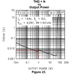
It is kind of strange that THD@1W is -100dB. TI shows -86dB. How did you get around the thermal coupling distortions, which are universal for all chip amps? Only composite amps are able to eliminate these distortions.
CMRR is not impressive but this is a common drawback of simple implementations like that. BTW I can't think of a single advantage of balanced over SE inputs when it comes to home use, just disadvantages.
No technical reason, just the feeling that the extra features/performance are not worth the corresponding size/cost/complexity. Perhaps an integrated balanced line receiver driving an LM3886 would be a better idea.Is there a technical reason not to use a buffer
Less that 1mV - the impedances at inverting and non-inverting inputs of the LM3886 are balanced, and its own offset current and offset voltage are low.DC offset
Just a large enough heatsink. When the LM3886 delivers 70W into 4 ohm, if the peak output voltage is just below clipping, the chip dissipates only about 20W. With θjc=1°C/W, this is not a problem as long as the heatsink is cool.How did you get 70W from 3886TF?
TI also shows THD+N=0.03% (that's just -70dB) @ 30W into 8ohm, and there are multiple LM3886 based amps that do better than this.THD@1W is -100dB. TI shows -86dB
Last edited:
I was particularly curious about the THD @ 1W and the way to get around the thermal coupling distortions.
BTW datasheets says - THD+N 0.0035% (fig. 22) not 0.03%. I have no doubt in the TI humbleness, always deliberately diminishing what the device is capable of.
BTW datasheets says - THD+N 0.0035% (fig. 22) not 0.03%. I have no doubt in the TI humbleness, always deliberately diminishing what the device is capable of.
A bit contradictory as it now is a too heavy load to many sources. Just 1 dual opamp to solve that.No technical reason, just the feeling that the extra features/performance are not worth the corresponding size/cost/complexity. Perhaps an integrated balanced line receiver driving an LM3886 would be a better idea.
Solving too low input impedance is worth extra cost.
At low power the heat transfer from the output stage to the input stage causes rapid temperature changes in input stage i.e. nonlinearity. This nonlinearity is the underlying cause for the bump in the THD plot around 1W. It is valid for any chip amp. At higher power the whole chip gets uniformly heated and the phenomena is gone.That's 0.007%, still pretty high. What makes you think this distortion is thermal?
One of the huge advantages of the composite amplifiers is that the input (the op amp) is no longer in physical contact with the output stage, i.e. eliminating the heat transfer and THD bump at 1W.
The lack of the bump is well visible in Kaltec's composite amps and neurochrome.
That's based on our experience with the Omicron, an inverting amplifier that was originally designed with the input impedance of 2kOhm and a frequency dependent crossfeed impedance in parallel. My signal sources, both test gear and music DACs and CD players, as well as those of a few early builders, were fine with this load. Yet, with quite a few Omicrons built, we found that raising the input impedance to 6kOhm works for a broader audience, even though there are still a few that prefer the 10kOhm version.too heavy load
BTW my board above has a version with a 10kOhm input impedance. It's a little noisier on measurement, but sonically is identical.
What's so special about 1W? Why not 0.5W or 2W? The physics of the process would not be much different, so I don't think thermal issues can cause bumps. The bumps, esp. the see-saw pattern seen in Figure 23 (see my post above) are usually measurement gear artifacts caused by gain switching.cause for the bump in the THD plot around 1W
Last edited:
1W is not specifically chosen, it just happens at that point. It happens at 0.5W and 2W as well but not to such an extent. There are many extensive studies on the subject. The most accessible one is D. Self - Design of power amps (or something like that).
I'm not trying to be negative, just curious about something that's been around for the last 30 years and very difficult to get rid of.
I'm not trying to be negative, just curious about something that's been around for the last 30 years and very difficult to get rid of.
You're not negative, just thoroughly off topic.
I suggest we close this off-topic discussion of thermal distortion and focus on the thread's subject instead.
It's me who's negative. When I hear "there are many extensive studies on the subject", I suspect the speaker simply doesn't know what he is talking about.
Let's read Douglas Self's excellent book you're referring to. I am looking at its sixth edition, and on page 120 the author says: "A third mechanism of very doubtful validity is thermal distortion, allegedly induced by parameter changes in semiconductor devices whose instantaneous power dissipation varies over a cycle". Then, on page 281, he says that "while now and again there have been odd mentions of thermal distortion in power amps in some of the hi-fi press, you'll never find: (1) any explanation of how it might work; (2) any estimate of the magnitude of the effect; (3) a circuit that will demonstrate its production." Not particularly supportive of the idea, huh? Then, on pages 282 and 283, he proceeds to say that thermal distortion does exist in IC power amplifiers because there is a dip in the distortion chart of the TDA1522Q at 40-60Hz that he cannot explain by anything else and thus assumes that the cause of the dip must be the thermal distortion. Ugh.
Now let's look at the "bumps". Here is a chart from the Audio Precision's APx555 B Audio Analyzers data sheet (link to the original document):
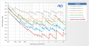
So many bumps, must be massive thermal distortion in four AP's and three competitive analyzers, right? Fortunately, no. As I said above, these bumps are caused by the analyzer's adjusting its gain, and hence the noise level, as the signal level changes.
Now let's just say thermal distortion exists, but you cannot detect it driving an amplifier with a 1kHz continuous sinewave as used for THD measurements. What you think is thermal distortion is something else, and thus your question "How did you get around the thermal coupling distortions?" is misguided. Sorry.
Let's read Douglas Self's excellent book you're referring to. I am looking at its sixth edition, and on page 120 the author says: "A third mechanism of very doubtful validity is thermal distortion, allegedly induced by parameter changes in semiconductor devices whose instantaneous power dissipation varies over a cycle". Then, on page 281, he says that "while now and again there have been odd mentions of thermal distortion in power amps in some of the hi-fi press, you'll never find: (1) any explanation of how it might work; (2) any estimate of the magnitude of the effect; (3) a circuit that will demonstrate its production." Not particularly supportive of the idea, huh? Then, on pages 282 and 283, he proceeds to say that thermal distortion does exist in IC power amplifiers because there is a dip in the distortion chart of the TDA1522Q at 40-60Hz that he cannot explain by anything else and thus assumes that the cause of the dip must be the thermal distortion. Ugh.
Now let's look at the "bumps". Here is a chart from the Audio Precision's APx555 B Audio Analyzers data sheet (link to the original document):

So many bumps, must be massive thermal distortion in four AP's and three competitive analyzers, right? Fortunately, no. As I said above, these bumps are caused by the analyzer's adjusting its gain, and hence the noise level, as the signal level changes.
Now let's just say thermal distortion exists, but you cannot detect it driving an amplifier with a 1kHz continuous sinewave as used for THD measurements. What you think is thermal distortion is something else, and thus your question "How did you get around the thermal coupling distortions?" is misguided. Sorry.
Hey, come on! What's the thread subject?
You published those graphics, remember?
I'm just discussing one of them.
If you're not comfortable with that, just say so. No worries.
But off the topic, no. It is right there.
Anyway, this's my last post in this thread.
You published those graphics, remember?
THD 1kHz 1W 8ohm (0.0010%):
I'm just discussing one of them.
If you're not comfortable with that, just say so. No worries.
But off the topic, no. It is right there.
Anyway, this's my last post in this thread.
1w is special because it represents 90% of music played. If your amp sounds great below 90db sound pressure it's good.
- Home
- Amplifiers
- Chip Amps
- Simple, compact, balanced input chipamp
