Of noise, you can expect the Johnson noise of various resistors combined with the noise of the LM3886 and scaled by the amplifier's gain. With such a simple schematic, the calculation is straightforward. Let me do the math because it is simple and can add color to the earlier suggestion to "reduce feedback resistors".
For simplicity, I omitted from the schematic all capacitors, lumped pairs of resistors in series together and shorted the input:

You place a noise voltage in series with each noise generating part and calculate the corresponding output noise voltage, assuming all other parts to be noiseless. For resistors, the noise can be found using the formula from Wikipedia or an online calculator. For the LM3886's noise, use the datasheet (it gives you an A-weighted value, which is lower than unweighted noise, but it is better than nothing).
For example:


Then you sum the noise from all the parts using RMS addition - that it, you square individual noise voltages, sum the squares, then take square root of the sum. In this case, you get 55.6μV. The measurement on the actual hardware gives me the same value. Note that even with the relatively high resistor values, the LM3886 is the biggest contributor to the total output noise.
Now let's make R1=R3=1kOhm and R2=R4=20kOhm and repeat the exercise. You get 45.2μV, just 1.8dB lower. The LM3886 now completely dominates the output noise.
You can repeat the calculation with other values and confirm that scaling the resistors can take you only so far.
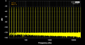
Of multi-tone, I am not a big fan. I believe that the test is hard to set up properly, hard to compare across different measurement setups, and hard to interpret in a way that helps development. Personally, I prefer IMD tests with various (non-standard) pairs of frequencies. However, since you asked, I took a multi-tone measurement with my QA403:

Here, the board runs from a +/-35V power supply with an 8 ohm load. The reference level (0dB) is 17.9V RMS, which corresponds to 40W into 8 ohm on a single-frequency sinewave. The test signal consists of 31 tones of equal amplitude, logarithmically spaced, three tones per octave. The total output level is just below clipping. The highest level intermodulation products are well below -115dBr.
For simplicity, I omitted from the schematic all capacitors, lumped pairs of resistors in series together and shorted the input:
You place a noise voltage in series with each noise generating part and calculate the corresponding output noise voltage, assuming all other parts to be noiseless. For resistors, the noise can be found using the formula from Wikipedia or an online calculator. For the LM3886's noise, use the datasheet (it gives you an A-weighted value, which is lower than unweighted noise, but it is better than nothing).
For example:
Then you sum the noise from all the parts using RMS addition - that it, you square individual noise voltages, sum the squares, then take square root of the sum. In this case, you get 55.6μV. The measurement on the actual hardware gives me the same value. Note that even with the relatively high resistor values, the LM3886 is the biggest contributor to the total output noise.
Now let's make R1=R3=1kOhm and R2=R4=20kOhm and repeat the exercise. You get 45.2μV, just 1.8dB lower. The LM3886 now completely dominates the output noise.
You can repeat the calculation with other values and confirm that scaling the resistors can take you only so far.
Of multi-tone, I am not a big fan. I believe that the test is hard to set up properly, hard to compare across different measurement setups, and hard to interpret in a way that helps development. Personally, I prefer IMD tests with various (non-standard) pairs of frequencies. However, since you asked, I took a multi-tone measurement with my QA403:

Here, the board runs from a +/-35V power supply with an 8 ohm load. The reference level (0dB) is 17.9V RMS, which corresponds to 40W into 8 ohm on a single-frequency sinewave. The test signal consists of 31 tones of equal amplitude, logarithmically spaced, three tones per octave. The total output level is just below clipping. The highest level intermodulation products are well below -115dBr.
Last edited:
Must admit noise calculation is revealing Alex. Didn't do it myself, but many members here are going for 1k and 20k FB resistors for noise reasons, leading to difficult to drive load in inverting or differential set up. Apperently it doesn't matter much, good read for anyone playing with this chip.