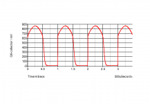
That looks normal. In a class AB amplifier, the lower output transistor will cut off when the output is positive, so the base voltage will fall to zero. When the signal phase is such that the lower output transistor turns on, the base voltage will be from about 0.6V (whatever the quiescent bias was) and rise to whatever Vbe is needed to achieve the output current (around 0.8-1V).
Simulated result attached. Remember, the upper output transistor has its emitter connected through the low value resitor to the output rail, so the base voltage is about the same as the output. The lower transistor has its emitter connected to ground and the base voltage only swings by what you have seen.
That situation would be different if you had a PNP output transistor, then both bases would be about the same as the output signal.
Attachments
Last edited:
If I inject a signal of 1Khz at 0.022Vrms I get out 1.4Vrms this is a gain of app 63 anything above 1.4Vrms and the waveform starts clipping, surely at 50V supply I should getting at least 15Vrms

- Status
- Not open for further replies.
- Home
- Amplifiers
- Solid State
- Simple circuit help