More voltage at low current means more noise and nastier pikes. I meant spikes 😀
The voltage level cannot reach 1.41 * secondary voltage when without load or small loads. Anything above that limit shows that something is wrong around there.
The voltage level cannot reach 1.41 * secondary voltage when without load or small loads. Anything above that limit shows that something is wrong around there.
Oh yes. And [so far] everything I've tried with it makes it worse. Ever had one of those dreams where you're stuck in a clothes dryer going around and around?
Apparently I missed a WHOLE BUNCH of posts. For some reason I was not getting notifications?
Anyway, While doing my usual weekly searches of ebay for interesting stuff, I happened across an Unregulated power supply from a surplus place. I think I can get it for less than $50 delivered.
It is +/- 24V 23AMPS. The specs from the manufacturer indicate that it has the following:
27V @ No Load
21V @ Full load (23AMPS)
Assuming the regulation is linear the Voltage at 12Amps should still be ^24V +/-
The datasheet also indicates that the +/- Outputs can be "floated" above ground up to 300V.
So I figure that I can use this to power both channels and then some. I have no problem with butchering this thing to make it work. It has a fairly large chassis of anodized aluminum and I am sure I can make it work aesthetically.
This is an "industrial" supply so the connections are external etc. I think there is plenty of room inside to rework that and include much more capacitance than is in there now.
I think for the time being I will use it as an external supply for prototyping/testing the feasibility of the amp. It has power to spare so a much more complex and powerful design can be done later.
Comparatively speaking I can get it delivered for less than 2 x 200VA Antek's and have 3 times the power available.
Need to check the email "spam bucket" click on diyaudio and click on the "not spam" button?
27v down to 24v, as in not monobocks like you wanted, risk of incessent clipping, risk of weird ringing, and even worse regulation than my current problem? I don't know, but I'm not sure that its worth the $50. Hey, I'm just playing with the MUR860's. I'll probably boot them off, in trade for more traditional technology that's more steady on voltage.
27v down to 24v, as in not monobocks like you wanted, risk of incessent clipping, risk of weird ringing, and even worse regulation than my current problem? I don't know, but I'm not sure that its worth the $50. Hey, I'm just playing with the MUR860's. I'll probably boot them off, in trade for more traditional technology that's more steady on voltage.
It is +/- 24V 23AMPS. The specs from the manufacturer indicate that it has the following:
27V @ No Load
21V @ Full load (23AMPS)
Assuming the regulation is linear the Voltage at 12Amps should still be ^24V +/-
GO FOR IT! That will be great for LMs.
GO FOR IT! That will be great for LMs.
Oh yes. That's right. He's got 25w to 30w midrange and treble amp and that's tube power (doesn't require as much headroom). For a chipamp to keep up on bass, that's like BPA200 or BPA300. The 12 ampers could be useful.
For the current project, just one of those antec's could run a pair of LM3886 or even a parallel pair, all still half price. It just depends on what you want to do.
Well, that's it: Definitely go for big amperage transformer if you're planning to bridge this rascal. Otherwise, you're paying too much for your transformer.
The Auction is ending in a few hours.
It is an Acopian "Gold Box" supply.
The dimensions are 11 1/4" L x 7 3/8"W x 5" tall
I am inquiring with the Mfr. as to exact specs. It appears in the basic schematic from their catalog that there is a Dual Primary or Center Tapped Primary in the unit for 115/230V operation. There also appears to be a Center tap on the Secondary.
I am also inquiring as to the type of rectifiers.
Per the schematic is also shows, a "Snubber Cap" and resistor across the +/- outputs. I am asking what those values are. Hopefully they answer before the auction ends.
I think I will bid up to $60 delivered for it. This thing is over $200 NEW and has more than enough power for what I might use it for.
I can put together a little board to go between it and the LM/Tube circuits I designed for a test and if I like what I have I am going to go in deep and create a version with a tube phase inverter and 4 chips per channel.
See the BPA-200 Documentation Figure 7. Similar to that except U5 is replaced with a "Split load phase inverter" based upon a very low-mu triode (6AS7G or 6080 a "cool looking tube") The lower pair of LM's would NOT be inverted. Essentially they are the same as the top pair. The SIGNAL would be inverted so in effect we get a "hybrid" push pull amplifier.
Some burnishing on that aluminum case plus some "Rustoleum Clear Lacquer" (wal-mart and other sources) can make a very pretty enclosure. That Lacquer takes several incomplete-looking coats (don't spray heavy) and then a polishing after 1 week. Its like glass then. It works just fine sprayed directly (several thin coats) onto aluminum or steel.
Got it for $39.31 delivered.
Also got answers from Acopian the Mfr.
It is a 125V primary CT secondary with LARGE 40Amp "Stud" type silicon diodes. Apparently in a Dual Half Wave setup (1 diode per half). It looks like the CT is grounded so you have +24V and -24V plus ground is 0V?
I am assuming it is a 40VCT secondary. That would explain 27.3 volts?
It has a 14,000uf Cap and 150R 10W resistor across the + and - leads.
Unfortunately the "Sales Engineer" that wrote me back could offer little more than a bogus generic schematic from the "instructions".
Working backwards from their output spec indicates NO load Voltage as 27V so 27/1.41=19.2 + 1.2V diode loss = 20.4V so I am guessing a 40VCT 1000VA tranny?
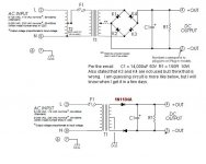
What do you mean by one diode per half? How many diodes are inside? Can you draw a schematic of it?
Guess: Perhaps its two diodes with a (72v?) center tap transformer to make a full wave rectifier?
It might be, but this doens't explain the differential output, unless if it's half-wave rectifier. If it's like that, then the power supply must suffer some changes, no doubt. Normally there should be 4 diodes, it's hard to believe that somebody still uses half-wave recitifiers. Diodes are't that expensive.
What do you mean by one diode per half? How many diodes are inside? Can you draw a schematic of it?
Here,
Attachments
It might be, but this doens't explain the differential output, unless if it's half-wave rectifier. If it's like that, then the power supply must suffer some changes, no doubt. Normally there should be 4 diodes, it's hard to believe that somebody still uses half-wave recitifiers. Diodes are't that expensive.
That is exactly what I thought. But my best guess is they Half Wave rectify each half of the tranny with CT grounded?
I am paying now and should have it in a few days.
BTW The LIST PRICE is over $300
Speaking of vacuum tubes, I'm up on the roof right now putting several vacuum tubes to work. I'm not so sure that 50 year old solid state could get the job done, but the tubes do just fine. And, thank goodness they're warm.
That is exactly what I thought. But my best guess is they Half Wave rectify each half of the tranny with CT grounded?
Hopefully it's the upper one but with CT grounded. If it's only half-wave I strongly recommend you to modify it otherwise it will be very noisy.
If its the other way around CT with full wave of 2 diodes is a 72vct transformer, you may be able to recycle it using regulators. One possible (and easy) example is: Building a Gainclone chip amp with a regulated power supply (PSU).
A regulator, after break-in, can lend a lot of extra power to the lowest notes, and this works because the rails neither raise nor sink, and therefore the bass notes have power in correct proportion. This can be especially thrilling with bridge amplifiers, like that BPA200/BPA300, which could really work out those car woofers.
PS. Its kind of fun that nobody, not even the manufacturer, has any idea what your power supply contains. 😉
Last edited:
Question: How much voltage do I have to drop to use a regulator (one per each rail, of course)?
Normally the voltage drop should be kept as low as possible. To get rid of the big ripple under full load you should have the voltage at the output regulator 2-3V less than the lowest voltage after filtering at full load. It also depends on the regulator. A big voltage drop will also mean a big power loss, which will be converted to heat. The power lost by the regulator is like this:
P = U * I
U is the voltage drop across the regulator
I is the maximum current through the regulator
P = U * I
U is the voltage drop across the regulator
I is the maximum current through the regulator
depends...use an auxiliary supply and you don't 'need' to have any drop at all. However ripple supression maybe poor, but voltage limitation is all you want or not?
Regards
Regards
- Status
- Not open for further replies.
- Home
- Amplifiers
- Chip Amps
- Simple Chip Amp for P to P wiring