Those of you who know the Classical Definition of the Cascode Circuit . . .
(For the most part that invention was before most persons reading this post were born)
Please give your comment on the circuits of Post # 11, and Post # 20.
Those are not Cascode amplifiers, Right?
Thanks for your participation in clearing up the mis-use of the Nomenclature: Cascode amplifier.
(For the most part that invention was before most persons reading this post were born)
Please give your comment on the circuits of Post # 11, and Post # 20.
Those are not Cascode amplifiers, Right?
Thanks for your participation in clearing up the mis-use of the Nomenclature: Cascode amplifier.
Last edited:
I went searching for cCCS-150 and found a thread where I asked this same dumb question, about 6 years ago.
LND150 gyrator for ECC83/12AX7 ???
None other than Rod Coleman replied with a good answer:
LND150 gyrator for ECC83/12AX7 ???
The thing to do is make a cascode CCS with a DN2540 on top and an LND150 in the bottom. About 50V needs to be dropped across the DN2540 for it to turn on hard enough to reduce its interelectrode capacitances to reasonable levels.
EDIT TO ADD:
I hadn't seen 6A3sUMMER's question about the proper use of the term 'cascode'. I'm using the term to apply to this configuration on a 'monkey see-monkey do' basis only. Pardon me if I'm using the term wrong. Thanks.
LND150 gyrator for ECC83/12AX7 ???
None other than Rod Coleman replied with a good answer:
LND150 gyrator for ECC83/12AX7 ???
If a cascode of about 1mA is desired, one way to increase the Vds of the lower device is this:
Replace the upstairs device with a part that requires more negative Vgs at the operating current. This is easy - the DN2540 will require more than 2V negative in this situation; compare the LND150, which requires almost 0V for the same current.
So try this: DN2540 upstairs, LND150 downstairs.
The thing to do is make a cascode CCS with a DN2540 on top and an LND150 in the bottom. About 50V needs to be dropped across the DN2540 for it to turn on hard enough to reduce its interelectrode capacitances to reasonable levels.
EDIT TO ADD:
I hadn't seen 6A3sUMMER's question about the proper use of the term 'cascode'. I'm using the term to apply to this configuration on a 'monkey see-monkey do' basis only. Pardon me if I'm using the term wrong. Thanks.
Last edited:
Those are not Cascode amplifiers, Right?
I think you misread something, nobody mentions "cascode amplifier".
The constant current circuit is "cascoded CCS".
You have a "current source" and a 270k resistor in series. Who is in charge here?
The JFET will break-down at 40V-50V Drain-Gate(and Source). Like a Zener diode. Fixed voltage. So no wonder there was no improvement. Performance was worse but not by so much it mattered.
Nope: you forgot the plate current, so the 270K will drop quite a bit of voltage, and so does the tube; as a result, the JFet sees only a few V. Yep, guaranteed: it survived years, until I decided to remove the silicon.
...
Would you please post a schematic of your JFet-Triode cascode?
...
Sure.
A few things:
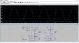
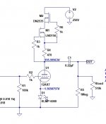
- This is not easy to reproduce because it's based on the super unobtanium 2SK147, plus it requires the selection of Rs for the desired Id and noise. You may get away with paralleled 2SK170 or equivalent
- This is an early iteration of the gain cell. I'm currently fighting some ground loops (of course), so I have no idea how it sounds. If it works, remind me to post the complete schematic.
- You'll need to rename z.txt to z.lib and put it somewhere LTspice can find
- The gain is 280, thanks to the high Gm of the 2SK147, H2 is -80dB, open loop, so maybe it's worth the trouble
Attachments
Last edited:
No way.
The J175 is a P-channel JFet; you'll need to invent and patent a "proton-tube" to go with, the one that takes negative plate voltage. 🙂
But do a search, there're still current production JFet that ressemble the 2SK170.
The J175 is a P-channel JFet; you'll need to invent and patent a "proton-tube" to go with, the one that takes negative plate voltage. 🙂
But do a search, there're still current production JFet that ressemble the 2SK170.
It looks like you could ground the grid of the 12AU7.
The 7V ds of the JFET would become the cathode voltage of the 12AU7, setting its grid bias (12AU7 grid would be at ground potential, so -7V from the 12AU7 cathode).
The 7V ds of the JFET would become the cathode voltage of the 12AU7, setting its grid bias (12AU7 grid would be at ground potential, so -7V from the 12AU7 cathode).
No way.
The J175 is a P-channel JFet; you'll need to invent and patent a "proton-tube" to go with, the one that takes negative plate voltage. 🙂
But do a search, there're still current production JFet that ressemble the 2SK170.
I don't know how I didn't notice that it was P-channel! /me feels stupid now.
Do you think a J175 would work?
I think a J309 would work. Not as glamorous (or as high gain, or as expensive) as an LSK170 or LSK389, but I think it would work.
Dumb question, but I'm not very good with SS parts... Could you make a "Darlington" with Jfets to get more gain? Cascode? For that matter, can you make a "Darlington" with tubes?
Well, I'm dumb with solid-state stuff too. My current project is proof of that! I'm having trouble with the right side going mute in this new phono preamp build. I have two FQPF2N70 MOSFET followers, one per channel. Troubleshooting revealed the right channel MOSFET starts to draw way too much current after the preamp's warmed up a bit. I thought that was a BJT trick... I don't know. I installed clip-on heatsinks and now they're both drawing the same 5.6mA Ids (current drain to source). I'm letting it bake for a little while to see if it does it again. Weird.
So, my dumb answer to your question is that you can certainly make a cascode out of two FETs. It's done all the time.
Can you make a Darlington? I dunno, so I looked it up. It makes sense that you can (if you want to), but there are downsides, which is why you don't see MOSFET Darlington pairs.
Can we use MOSFETs to make a Darlington pair? Is it true that it will give us a very high gain at midband frequency? - Quora
A Darlington pair with tubes would be even worse. High interelectrode capacitance, limited gain, lots of Miller effect reducing bandwidth. However, I'll bet really smart people can make it work. Someone will probably pop in with one.
--
It looks like you could ground the grid of the 12AU7.
The 7V ds of the JFET would become the cathode voltage of the 12AU7, setting its grid bias (12AU7 grid would be at ground potential, so -7V from the 12AU7 cathode).
Correct: this is one valid option that was considered, but rejected.
On the one hand, it's simplicity and better isolation from the power supply, on the other hand, it's much harder to get the other parameters right, such as Id of 5mA or more, Vds of 7V or more, etc. A voltage divider lets me tweak these sweet spots much more easily.
Good point. Did you run into problems when you grounded the grid of the 12AU7? Was the problem that the FETs vary enough that each one had to have its source resistor (Rs) adjusted on test?
A hybrid cascode like that is on my list of things to try as I get more experience. I was thinking of making a stereo pair using an LSK389 (matched pair of LSK170 on a single die). That way I'd only have to tweak once.
I was also thinking of using a pair of 6V6 wired triode on top. That has a larger grid base, so will yield more Vds for the FET to work within. Of course it's a beam tetrode, so it will have to be triode wired. That's not a big deal. The big octal tubes would look cool too. You could even use metal ones if you have 'em, for that 1940s vintage look. 😎
No, I just SIM the hell out of it before I commit to the soldering iron.
The major difficulty is to guess at what would make the JFet happy (operating point), then decide on a Rs that could achieve this, then measure the physical JFet with that Rs to confirm, then plug the measured Gm (Yfs) back into the simulation model, then try a bit higher/lower, adjusting Rp (load resistor) all the while, until you're bored silly. 🙂
The K170/K389 are good candidates if a bit pricey. There're others, maybe the CPH3910. Much have been posted right here on the replacement of the K170, do a search for the current situation.
Makes sense, right? Miller effect. LND150 has very low hfe for a transistor, so internal capacitances are lower than in other transistors. But much less gain is available. However, that's still a bit more gain than a 12AX7.
So why can't I find a hybrid LND150-12AX7 mu follower anywhere? Strange.
I've found a lot of projects like 'making a solid state Marshall JTM800 preamp'
The LND150 is a MOSFET, which isn't characterized by hfe, but by mu (transconductance)
Hi,
I would like to ask what is the impedance vs frequency seen by the 12ax7 with the LND150 CCS.
How to calculate the midband impedance with a LND150 starting from the resistor that sets the current, and how to calculate the frequency at which the impedance starts to drop.
Thanks.
I would like to ask what is the impedance vs frequency seen by the 12ax7 with the LND150 CCS.
How to calculate the midband impedance with a LND150 starting from the resistor that sets the current, and how to calculate the frequency at which the impedance starts to drop.
Thanks.
Zintolo,
Thanks for your question!
You have just made me aware of a great solid state part.
I only use solid state parts if it makes sense to me (example, I use solid state rectifiers).
This part looks like a winner to me, I want to try it (the old build and test method; simulation is for other people).
Here is the data sheet to the LND150:
https://www.digikey.com/htmldatasheets/production/1609561/0/0/1/lnd150.html?utm_adgroup=xGeneral&utm_source=google&utm_medium=cpc&utm_campaign=Dynamic Search_EN_Product&utm_term=&utm_content=xGeneral&utm_id=go_cmp-120565755_adg-7526266635_ad-398891859253_dsa-19959388920_dev-c_ext-_prd-_sig-EAIaIQobChMIw4qi_L37ggMV8RutBh2mMwqtEAAYASAAEgKEM_D_BwE&gad_source=1&gclid=EAIaIQobChMIw4qi_L37ggMV8RutBh2mMwqtEAAYASAAEgKEM_D_BwE
Looking at the data sheet, I make the following observations and estimates:
Longest time rating is the Fall Time; typical 1.3 usec. 0.35/fall time = bandwidth of the part. 0.35/1.3usec = 270kHz
The gate to source capacitance is about 8 pF. If you can keep your wiring stray capacitance, and the 12AX7 plate capacitance, and the following tube's grid capacitance to 8uf or less (I doubt that), the LND150 is 1/2 of the contributor of the 12AX7 stage high frequency bandwidth. Otherwise, the rest of the circuit, not the LND150, is the high frequency bandwidth determinant.
I like the part, it is listed as a Depletion Mode part, even though it can also be used in the enhancement mode.
However, I would Only use it in the Depletion mode.
The first (upper left) curve, Output Characteristics, . . . at a 1.8mA current is as flat as a pancake. That shows the midband impedance to be very high.
The above are just my thoughts and estimates, so for me, building and testing is what I need to find the results (have to see if my friend has some LND150 parts, or I will order some).
Looks like a good CCS for my 12AX7 and 5751 tubes.
Keep posting.
Have Fun!
Last edited:

Thanks @6A3sUMMER !
Curious to see what you’ll find out.
I’ve found this article:
https://www.bartola.co.uk/valves/2015/08/31/ccs-not-everything-that-glitters-is-gold-part-i/
Where it explains:
“So the output impedance is set by mu times the Rset. A big value indeed can be achieved. For example using the famous DN2540, at about 30mA of drain current (Id) the gm is 240mA/V and rds is 14-15kΩ @Vds<1V. This yields to a μ of 3,600.”
LND150 has 2 mA/V, but how to find the Rds in those conditions? Thanks.
- Home
- Amplifiers
- Tubes / Valves
- Simple building block for high gain preamps - 12AX7 with single LND150 for CCS?