Relay contact can go in typical CT connection to 0V. Diodes will see in-rush levels consistent with effective transformer series resistance, plus any additional primary NTC. Can put a bleed resistor across contact to provide partial pre-charge of main filter cap, and hence reduce in-rush. Can put MOV's across secondary HT section to alleviate turn-off transients under load conditions.
Other issues with relay contacts include (1) contact bounce, (2) arc quench on contacts opening, and as pointed out with respect to voltage rating, voltage/current rating.
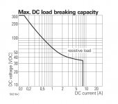
As the voltage goes up the current rating goes down, rapidly. Most of the small relays I've seen suggested or used are overstressed.
A relay with a general purpose rating of 100,000 cycles at 10A 250VAC (8A 30VDC)may only be good for a couple thousand cycles when pushed to 300VDC where the current rating drops to 100-200mA.
Here is a chart showing a typical derating curve Notice the current at 300VDC drops to 150mA. This relay can not be relied upon to quench much above 300VDC. Contact life is very short. :
Attachments
Wavebourn, the Rubli delay board does not switch "abruptly", the timing circuit passes a small parasitic current which pre-charges the caps downstream.
Your regulator looks interesting, but I don't see how it "waits for tubes to warm up". Can you explain that part?
Your regulator looks interesting, but I don't see how it "waits for tubes to warm up". Can you explain that part?
Wavebourn, the Rubli delay board does not switch "abruptly", the timing circuit passes a small parasitic current which pre-charges the caps downstream.
In such case it is inrush current limiter that is good, not a relay - based B+ delay that would be bad.
Your regulator looks interesting, but I don't see how it "waits for tubes to warm up". Can you explain that part?
Pass - regulator for B+ and shunt regulator for bias are connected in series and powered from the same rectifier sharing the same current. Load for B+ is connected in parallel with output of pass regulator, that means current that goes through shunt regulator charges it's capacitor, and speed of increase of this voltage is proportional to current through load. That means, while tubes are cold increase of voltage is very slow, but as soon as tubes start drawing current speed of increase of the voltage increases.
It causes also proportional increase of B+ voltage supplied by B+ pass regulator, since it gets it's reference voltage from shunt bias regulator.
Ha ha ha, OK I see. You are saying the tubes draw current, therefore they must be warm. Well, maybe. Or maybe you have many cold tubes drawing a little bit of current each. Or maybe there are voltage dividers, large electrolytics or other things in the circuit that all draw current. Not exactly a universal circuit.
Back to the OP topic, I think the OP was asking about a time delay circuit that would work on pretty much any amp. Yours would have to be designed specifically for each.
Back to the OP topic, I think the OP was asking about a time delay circuit that would work on pretty much any amp. Yours would have to be designed specifically for each.
Relays, like switches, shouldn't really be used for HT DC supply lines - that is often poor design as many parts have no DC specs at all, and as the Gimp points out - anticipated contact life plummets. The simplest typical AC position is the CT to 0V, as only one contact is needed. A 250VAC rated contact is going to generally have a good chance of operating for valve rectifier inputs, as the capacitive load and series resistance leads to minimal current surge levels.
Ha ha ha, OK I see. You are saying the tubes draw current, therefore they must be warm. Well, maybe. Or maybe you have many cold tubes drawing a little bit of current each. Or maybe there are voltage dividers, large electrolytics or other things in the circuit that all draw current. Not exactly a universal circuit.
Back to the OP topic, I think the OP was asking about a time delay circuit that would work on pretty much any amp. Yours would have to be designed specifically for each.
...or may be you need some education before writing such "ha-ha-ha"? 😉
Are you sure OP really needs what you are proposing? What is the purpose of B+ delay? Can you explain me please, what do you achieve delaying B+ except obvious "Some folks recommended"?
Schematic of simplest way I know of........... SS bridge coupled to the amp through a diode as a thermal switch, it starts with the rest of the tubes and the B+ slowly rises without overshoot. I've tried it with and without the inductor will little change. By theory there should be another cap at the inductor to diode connection for best results.
Attachments
...or may be you need some education before writing such "ha-ha-ha"? 😉
Are you sure OP really needs what you are proposing? What is the purpose of B+ delay? Can you explain me please, what do you achieve delaying B+ except obvious "Some folks recommended"?
I'm not sure of anything regarding what the OP needs. He asked a specific question and I offered one possible solution, like others (and you) have.
As to what I achieve with B+ delay, sometimes nothing needed and I don't use it. When I do, it's mostly so I don't have to listen to various sonic artifacts as various tubes come alive at different times. A secondary effect that I like is that any filter caps downstream of the "delay" are charged slowly if the delay has a "leak". Depending on the topology, diodes and filter caps used, it may be beneficial not to have a huge inrush spike.
Is this not why "some folks recommend it"? 🙂
I kind of like the idea of a relay across a moderately high value resistor in series with the B+ between the rectifier and first cap.
Use a time delay to turn on the relay with a long enough RC time constant so the B+ is still rising after the tubes are warmed up.
Personally the only reason I use a delay at all is with guitar amps where I have a standby switch if the caps may see a surge above their rating if a standby switch were not present.
Delay of B+
I took a different approach. I had an issue with the operating voltage on the filter cap and changed from a 5AR4 to a 5U4 which dropped the voltage about 25v. The problem was that the 5AR4 was indirectly heated and the voltage at turnon was about 534 before settling back to 503. With the direct heated 5U4 the voltage spiked to 568.
So I devised a relay that is placed in series with the filament of the rectifier, is powered by the filament voltage, uses 5v relay and 10v caps for small size, and delays the power up of the rectifier by 20s which gives ample time for the output tubes to heat up and present a load plus the slow ramp of current from the tube. Doing this kept the surge at startup to less than 490v. Simple cheap and no special circuit, just a relay, diode, filter cap, RC timing and Transistor to drive relay. Resets in 1/2sec when powered off.
Attachments
I use a thermistor in the B+ primary for slow warmup . After about a minute, this is bypassed by closing a simple timed relay
in my 6c33 build, i used a 2.7k, 3W resistor in series with the rectifier and the first filter cap, after a delay of about 2 minutes i shorted out the resistor by relay contacts..
I posted this elsewhere - in Robert Tomer "Getting the most out of vacuum tubes" it is mentioned that the rectifier needs to start conducting around the same time as the current draw ramps up. If this is not possible then the rectifier needs to be warmed up before the current draw starts. (something along those words may have been said differently, content is accurate). I use some thermistors in series witht he rectifier tube and bypass those after a while. Soft start B+ for both rectifier tube and the audio tubes.
The Tomer reference may require some more discussion. Tomer describes the damage cause to rectifier diodes on pages 18-19, where the diode cathode has not sufficiently heated to a level where space charge around the cathode can support the demanded current from the power supply/load, and so a 'very heavy current demand' can cause spots on the cathode to be damaged, which can develop in to an arcing episode.
The damaging aspect of this type of event is the arcing episode, whereby within half a mains cycle the diode may continue to arc from cathode to the reverse biased anode, as a form of high power short circuit. In Tomer's day (1960) they didn't have the ability to add an ss diode in series with the valve diode's anode to prevent reverse conduction/arcing from a poor valve diode.
The other aspect to discuss is Tomer's 'very heavy current demand' comment. All valve diodes have a peak current rating, and in particular a peak short term current rating of typically 0.2 sec (ie. 4 mains cycles) where the diode cathode is robust enough to charge up filter capacitance during expected nominal power on events. If the power on surge current requirement of the supply capacitors and amp circuitry exceed that diode rating then sure there is a design need to alleviate the situation.
In general, if the ratings for a valve are not being exceeded, or operating conditions are not stressing the valves close to or beyond the ratings, then imho adding additional parts and processes have no technical justification (ie. based on statistically observable failure rates).
Last edited:
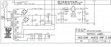
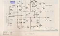
Delay I Used in Crowhurst's Twin Coupled Amp
Complete Article published in AudioXpress Magazine 2004.
All put on a pdf with added information a few years ago.
The line up is a 2-stage diff amp, 6SL7 & 6SN7 followed by PP 6LU8s.
More than 35 watts at clipping & easily scalable for more power.
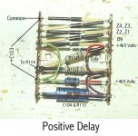
Delay controlled by R116 & C103.🙂
Complete Article published in AudioXpress Magazine 2004.
All put on a pdf with added information a few years ago.
The line up is a 2-stage diff amp, 6SL7 & 6SN7 followed by PP 6LU8s.
More than 35 watts at clipping & easily scalable for more power.
Delay controlled by R116 & C103.🙂
Attachments
WARNING!Complete Article published in AudioXpress Magazine 2004.
All put on a pdf with added information a few years ago.
The line up is a 2-stage diff amp, 6SL7 & 6SN7 followed by PP 6LU8s.
More than 35 watts at clipping & easily scalable for more power.
Delay controlled by R116 & C103.🙂
This schematics connects one leg of the mains to chassies ground !!
Equivalent to a "hot-chassies" design.
I think the connection could be removed without any problem.
Complete Article published in AudioXpress Magazine 2004.
What's the purpose of C104 & R113 on the cascoded MOSFETs?
Correction
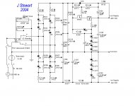
THX to Peter who actually looks at the stuff I post!!. Last night I simply searched my archive for that schematic, this one popped up. It is a preliminary drawing that never got to the publisher.😀
THX to Peter who actually looks at the stuff I post!!. Last night I simply searched my archive for that schematic, this one popped up. It is a preliminary drawing that never got to the publisher.😀
Attachments
Yes, this one is safe to use, at least regarding isolation from mains.THX to Peter who actually looks at the stuff I post!!. Last night I simply searched my archive for that schematic, this one popped up. It is a preliminary drawing that never got to the publisher.😀
- Home
- Amplifiers
- Tubes / Valves
- Simple B+ delay circuit for tube power amp?