In the possible case you missed some courses at school, here are some rather good pages with many different tutorials:
https://learn.sparkfun.com/tutorials/how-to-read-a-schematic/all
At the bottom of the page you look at 'Resources and Going further'.
One page a day will keep the doctor away 🙂
Hugo
https://learn.sparkfun.com/tutorials/how-to-read-a-schematic/all
At the bottom of the page you look at 'Resources and Going further'.
One page a day will keep the doctor away 🙂
Hugo

GND is at the negative of the power supply.And the GND? In reality electronics, where does the GND connect?
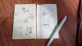
It is a voltage follower. Voltage gain in the configuration I have shown is about 0.85 x. It is still good if you drive it from CD output or mp3 player headphone output. Input impedance is 500 - 700 ohm, depending on transistor h21e. Output impedance is 1 - 4 ohm, depending on source impedance. The lower output impedance of the sound source, the lower the output impedance of the “amplifier”. Anyway, this one-transistor amp would be an ideal start to understand transistor behaviour, if you are willing to learn.
Hi Pavel,
It would be nice to explain how you did the calculation for this little circuit with a few simple formulas.
I might learn a thing or two as well 🙂
Hugo
It would be nice to explain how you did the calculation for this little circuit with a few simple formulas.
I might learn a thing or two as well 🙂
Hugo
Hi Hugo,
I agree, I was thinking about preparing something as you have suggested. This might help the beginners and future diyaudio circuit enthusiasts. Analog design is vanishing these days.
Pavel
I agree, I was thinking about preparing something as you have suggested. This might help the beginners and future diyaudio circuit enthusiasts. Analog design is vanishing these days.
Pavel
Pavel, your circuit is even simpler than NP first and only watt (FAOW). What is bias accross c5200? I wonder if it would benefit from increasing it?
I got lots of c5200s, i can try to push 1.5A through on big heatsink. Maybe next week, i am traveling now.
I got lots of c5200s, i can try to push 1.5A through on big heatsink. Maybe next week, i am traveling now.
Hi Pavel,
It would be nice to explain how you did the calculation for this little circuit with a few simple formulas.
I might learn a thing or two as well 🙂
Hugo
Hi Hugo, starting with DC analysis, I hope it is understandable.
I all honesty it should be called buffer, not an amp, since its gain is less than one.
Hi @adason , it is questionable, because the circuit has POWER gain, it amplifies current into the load. It has CURRENT gain, it has not VOLTAGE gain. There are opposite examples of circuits with VOLTAGE gain and no CURRENT gain, like common base transistor circuit. Again, it has POWER gain.
If circuit amplifies voltage, but not current, i would call it preamp.
Just curious, what's current through c5200?
Just curious, what's current through c5200?
Even I do 🙂I hope it is understandable
How do you initially select Rb and Re?
And why do you write h21E instead of hfe? What is the meaning of 21?
Hugo
Hi Hugo,
re h21, it is a two-port common notation, please see this excellent app note
https://toshiba.semicon-storage.com/info/application_note_en_20210127_AKX00050.pdf?did=63511
I do the choice of Rb and Re based on my professional guess 😀, then I verify by calculation or simulation. You may use the equations that I posted, Ic and V(Re) and h21 (beta) will be your input variables and you will calculate the rest.
It would take ages for me to decifer what's in that app note but
it's enough for me to understand that h21e stands for hfe or beta.
a page for how to calculate in- and output impedance of a circuit:
http://www.sengpielaudio.com/calculator-InputOutputImpedance.htm
From the above I note that both are related to each other in this particular case.
Hugo
it's enough for me to understand that h21e stands for hfe or beta.
Now that you learned us how to calculate the DC values, I can addThe lower output impedance of the sound source, the lower the output impedance of the “amplifier”
a page for how to calculate in- and output impedance of a circuit:
http://www.sengpielaudio.com/calculator-InputOutputImpedance.htm
From the above I note that both are related to each other in this particular case.
Hugo
I am sorry, but the linked calculator cannot calculate amplifier's input and output impedance and how the load impedance of the BJT follower affects its input impedance and how source impedance affects follower output impedance. You need to use either two-port analysis with Y or H matrices, or full description by circuit equations, or circuit simulator like LTSpice or MicroCap, which is the fastest way. Shortly, input impedance of the follower circuit is approximately (h21 * Re (or Rload)) // Rb resistor.
Ic i see 0.3A.If circuit amplifies voltage, but not current, i would call it preamp.
Just curious, what's current through c5200?
Sorry, have not seen your image before.
I realise that in this simple circuit the in- and output impedances are too depended on each other.
I presume this is not or less the case in more advanced circuits.
For the input impedance of this circuit we would then have +/- 100*15 // 2200 which would be 900 Ohm.
Thanks Pavel.
Hugo
I presume this is not or less the case in more advanced circuits.
For the input impedance of this circuit we would then have +/- 100*15 // 2200 which would be 900 Ohm.
Thanks Pavel.
Hugo
I like playing with these super simple circuits. Below is a response to 100kHz sine and 10kHz square. Both input and output (10 ohm load) shown, input is CH1/blue, output CH2/yellow.


- Home
- Design & Build
- Electronic Design
- Simple amplifier circuit