Just to take an evolutionary step further, I wonder if OP would benefit from a design using an op-amp with the transistor? Say, +/- 5V rails, which should be easy to do with a couple 5V wall warts (I've seen them in multi-amp capacity...), and the op-amp behaving as servo to make the transistor emitter be at 0V, allowing a speaker connection without the big cap. Maybe helps with the input impedance concern too.
Sounds like something you could ask "Chat GPT" to design. Especially when they get the Q* thing going, which I guess lets it think in math.
Sounds like something you could ask "Chat GPT" to design. Especially when they get the Q* thing going, which I guess lets it think in math.
Of course it would help, the question is a degree of complexity he wants to accept. The easiest way to increase input impedance is to use Darlington at Q1 position, like TIP131, and to increase R2 base resistor. Output impedance is good even now, I have just measured 0.35 ohm.
BTW, below is my, 22 years old similar project 🙂.
https://sound-au.com/project83.htm
BTW, below is my, 22 years old similar project 🙂.
https://sound-au.com/project83.htm
Instead of using Darlington, we could expand the circuit to 2 transistors:
BD139 + Power transistor, making it a Darlington follower.
BD139 + Power transistor, making it a Darlington follower.
Fantastic, Pavel.BTW, below is my, 22 years old similar project 🙂.
Usually the typical textbook example on how to properly bias a single common collector gain stage uses a resistor divider between Vcc-base-GND, with just one resistor between Vcc-base the DC operating point would be more temperature dependent due to the temperature dependent hfe.
Good point, but, these are the real life results: idle current starts at 295 mA for the “cold” device (room temperature 22C) and rises to 312 mA after the heatsink temperature has stabilized at 43C. This is, to me, unimportant. Using a divider instead of a single Rb resistor would lead to inevitable decrease of input impedance, which is quite low even now. We need base current of some 3mA to keep emitter current at 300mA. Emitter current cannot be further decreased, the usable output voltage/ power would be TOO low. Base divider would eat a part of base current, or, if made with smaller resistor values, it would decrease input impedance. This would be too high price for marginal improvement of idle current stability, which is not very important in a class A buffer.
When i worked on my bjt buffers, i too realized that we need to provide some current to feed the base of c5200. I stole the idea from fm acoustics amp and used another c5200 to drive it.
That allowed me to triple the outputs.
I measured Ic vs distortion, and settled on 0.3A per bjt. Driver much less, no heatsink.
Offcourse i worked out symetrical buffer with a1943 and +/_23 Vdc. Distortion was quite low, comparable with NP F4 buffer.
Absolutely no global negative feedback maintained beautifull soundstage. I built quite a few of these with various complementary bjts. They all worked great and deserve to be finished into final enclosure.
They need good pre to drive them to 20 watts though.
https://www.diyaudio.com/community/threads/output-bjts-for-buffer.386324/
@PMA Thanks for your reply and explanation, I emphatically agree with your reasoning so no doubt here, looking at the simple emitter follower buffer what interested my curiosity was with respect to temperature stability, I think the relatively large emitter resistor with regards to Ic do much to help here, any tendencies seeing an increased Ic, or Ie if one will, will increase the Vf over that resistor and thereby decrease Vcb, that in turn reduces the current through the single base resistor which now counteracts 'thermal runaway', the proof in the pudding is in your practical circuit, I admit I was a bit surprised the Ic was after all more stable than I did saw at a first quick glance, well done and a good back-to-basic starter for newbies and refresher for oldies.
That aside, just some off-topic pondering here, I more recently often wonder why people are still so obsessed with input impedance's and that as high an input impedance is something highly sought after, in the current world most modern sources of audio equipment we have today can handle anything starting with something like a lowish 1kOhm with ease and barely no compromise to the signal fidelity, maybe a historical reason why high input impedance was a necessity, or perhaps I am short of memory overlooking something for the moment.
That aside, just some off-topic pondering here, I more recently often wonder why people are still so obsessed with input impedance's and that as high an input impedance is something highly sought after, in the current world most modern sources of audio equipment we have today can handle anything starting with something like a lowish 1kOhm with ease and barely no compromise to the signal fidelity, maybe a historical reason why high input impedance was a necessity, or perhaps I am short of memory overlooking something for the moment.
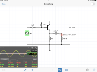
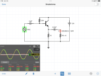
The input impedance here, depending on load, is plotted below. This is with a single 2k2 base resistor. This is just at the limit to be driven from 50 ohm generator impedance. So maybe it is not only an obsession. If the base bias divider was used, with resistor values that would bring some useful temperature stability improvement, the input impedance would fall to a half of the current one. You were right in your post #1 in general, however, we always need to take the real circuit values into account.
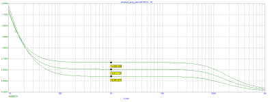

That aside, just some off-topic pondering here, I more recently often wonder why people are still so obsessed with input impedance's and that as high an input impedance is something highly sought after, in the current world most modern sources of audio equipment we have today can handle anything starting with something like a lowish 1kOhm with ease and barely no compromise to the signal fidelity, maybe a historical reason why high input impedance was a necessity, or perhaps I am short of memory overlooking something for the moment.
First, many of the industry standards for hi fi were established way back in the day of tubes. Without a cathode follower buffer, a tube line level stage would typically struggle to even drive a 47K input impedance. Line level input impedances were 100K min (470K-1 Meg typical).
Input impedance affects low frequency cutoff of capacitor coupled cutoff stages. Reducing input impedance from 10K to 1K would raise the frequency ten times; in other words if the low frequency cutoff was 10 Hz into 10K then it would be 100 Hz into 1K.
If you want your designs to be compatible with the majority of sources, then 10K minimum input impedance is good practice. All the line level equipment I design and build has a uniform 47K input impedance and 100 ohm output impedance. This ensures near universal compatibility with virtually any commercially built equipment from about 1970 to the present.
"I will build this funny amplifier on a PCB" That "funny amplifier" is remarkably linear considering the parts count and simplicity. In fact it was employed as a buffer in commercial equipment for the first 15 years of transistor audio equipment.
EDIT: Figure 13 https://sound-au.com/articles/followers.html shows a practical and useful discrete unity gain buffer.
EDIT: Figure 13 https://sound-au.com/articles/followers.html shows a practical and useful discrete unity gain buffer.
Last edited:
Yes, but I was talking about simplest possible 1-transistor power buffer, that would be able to feed the speaker. Such task needs low output impedance and reasonably low distortion. The new thread is here:
https://www.diyaudio.com/community/...wer-amplifier-with-thd-1.406538/#post-7533512
Regarding Rod Elliott pages, I published Project 83 (Mosfet power follower) there in 2001. It was designed for huge heatsink. It has had much higher input impedance than the BJT power follower, but it was more complex (CCS). The goal now has been Simplest Possible, but with acceptable parameters. This resulted in 2 resistors, 2 capacitors and 1 transistor as necessary components.
That's the kind of circuit I learned on, way back when I was ten years old. It's an excellent circuit to build for the purpose of learning electronics.
Can you imagine if there was a way for Us to get together back then? It seems there were a number of folks around the world doing that same circuit at the same time. Oh, OK - I'll guess if the tech were available to "get together", that would probably preclude any interest in the little amplifier circuit in the first place! One of the gifts of that era was you got to be bored some of the time and consequentially looked for something to do.way back when I was ten years old.
Ok thanks for the tidbits @Fast Eddie D , makes sense for the Freddy Flinstoners, jokes aside, no I don't disagree on that, so thanks for the flashback refresher why high input impedance may be needed, will keep that in mind when i'm getting into the highend biz.
But for the rest (the younger generation), will grab their mobilephone (w/wo DAC dongle etc), HPA or whatever typically with a 6,3/3,5/2,5mm plug and it probably drives if not very far off even down to 32Ohms.
Anyhow, no, I don't necessary promote for designing gears with very low input impedance, my previous post sprung out partially as a reaction to the very limited design constraints round a single BJT amp, however, we DIY tinkeres have some more leeway designing our stuff, have fun with Pavel's "Simplest possible 1-transistor power amplifier with THD <1%" everyone, I should give it a try too.
Any cellphone can easily drive a low impedance input obviously. With this simple buffer you could easily drive an 8 ohm speaker to modest volume.
Add voltage gain to the amplifier (two stage) and you could drive an 8 ohm speaker with a couple watts (using a 12 volt supply), which is plenty for near field listening.
Add voltage gain to the amplifier (two stage) and you could drive an 8 ohm speaker with a couple watts (using a 12 volt supply), which is plenty for near field listening.
- Home
- Design & Build
- Electronic Design
- Simple amplifier circuit
