My monobloc amps each use 3 x 6c33c, two with a single triode heated, one with both triodes heated. A 12.6V 6.6A transformer is directly wired to to the three tube sockets such that all the 6c33c heaters receive 6.3vac or thereabouts. The amps have many thousands of hours on them and a couple of years ago I had a heater transformer burn out and the AC wiring began to melt the insulation. At the time I put it down to a 6c33c failing in such a way to increase the AC draw (i.e. a short circuit) thus causing things to get hot and eventually fail. No fuse on the heater circuit...everything direct wired. Replaced transformer and wiring and set to listening a lot more.
Today, this has happened again (with probably another 6,000hours on the amps in the meantime) about six hours into the days playlist and I believe it is more than bad luck with a tube failiure, it is now a design flaw. But I am having trouble trying to figure out why this is occuring.
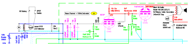
Filaments are floating although the transformers are centre tapped so could be elevated if necessary. The 6c33c plates are 200V/240mA and 190V/150mA depending on whether the tube has one or two triodes heated. Cathodes are directly grounded (no caps or resistors to ground) and the amp uses a 150V bipolar supply to generate an adjustable grid bias (and eliminate the input capacitor). See attached snippet of schematic. In the schematic Dark Blue is signal positive (+150V from bias supply), Light Blue is Signal Ground, Dashed Light Blue is connected to 0V in the bipolar bias supply, Signal Ground, Green is -150V bias, Dashed Green is connection to chassis ground, Red is B+. The 6e5p's have a heater supply separate to the 6c33c.

This is not quite your normal SET amp arrangement but the sound is glorious, so when repaired I would like it to not fail this way again so am calling for help. Any ideas for why this amp melts heater wires from time to time?
Today, this has happened again (with probably another 6,000hours on the amps in the meantime) about six hours into the days playlist and I believe it is more than bad luck with a tube failiure, it is now a design flaw. But I am having trouble trying to figure out why this is occuring.
Filaments are floating although the transformers are centre tapped so could be elevated if necessary. The 6c33c plates are 200V/240mA and 190V/150mA depending on whether the tube has one or two triodes heated. Cathodes are directly grounded (no caps or resistors to ground) and the amp uses a 150V bipolar supply to generate an adjustable grid bias (and eliminate the input capacitor). See attached snippet of schematic. In the schematic Dark Blue is signal positive (+150V from bias supply), Light Blue is Signal Ground, Dashed Light Blue is connected to 0V in the bipolar bias supply, Signal Ground, Green is -150V bias, Dashed Green is connection to chassis ground, Red is B+. The 6e5p's have a heater supply separate to the 6c33c.
This is not quite your normal SET amp arrangement but the sound is glorious, so when repaired I would like it to not fail this way again so am calling for help. Any ideas for why this amp melts heater wires from time to time?
Attachments
I deleted my message, math was wrong 🙂
But heater current, per section, is 3.0...3.6A, combined 1/2 + 1/2 + 1, could be a bit above 6.6A, depending on lady luck.
But heater current, per section, is 3.0...3.6A, combined 1/2 + 1/2 + 1, could be a bit above 6.6A, depending on lady luck.
Are you able to measure the real total heater current? It would probably be better to use a more powerful transformer anyway, if space is not an issue.
Measured during build and testing with a few tube compliments at 6.6A, right on spec. The transformers are custom wound, low heat gain EI core that normally run quite cool... only 10 degrees celsius or so above ambient.
When I get a moment I plan to run the 6c33c and 6e5p in the amps at the breakdown through my Etracer to try to determine if any have failed. Q
When I get a moment I plan to run the 6c33c and 6e5p in the amps at the breakdown through my Etracer to try to determine if any have failed. Q
seems to be a long term issue;
there were reports that heater socket terminals with 6c33c can get hot enough to melt lead/tin based solder;
think of a scenario like this:
in the long run heater pin solder joints melt and / or corrode, get loose;
solder joint resistance rises, causing more local heat;
insulation next to socket terminals burns and melts first;
finally naked wires of tightly twisted ac lines touch causing a dead short;
you could try teflon insulated wire and lead free solder with a higher melting point;
and I would inspect heater line solder joints initially every 100 hrs or so rather than wait another 6000;
and a transformer primary fuse or a toroid with a built in thermal fuse is mandatory to prevent fire ...
Last edited:
This is not OK , and could be the cause of failure . Elevate the filaments or connect the center tap to groundFilaments are floating although the transformers are centre tapped so could be elevated if necessary.
@Sorento yes, that does make sense. An easy fix too. Your description of the events leading to the overheating seems to be accurate but I will know further when I pull the amplifier apart for inspection. This time I think I caught it quite early...there was a sniff of melting plastic and I saw what I think were the first whisps of smoke so I turned it off. The heater wiring insulation is discoloured about 2cm from the socket and I think the rest will be in decent condtion and the transformer unharmed...but that remains to be seen.
I'm considering a temperature sensor on the filament wiring near the tube socket that could be used to trigger the power-off function on the logic board so that the entire power supply is turned off, not just the 6c33c filaments when a fuse blows.
I'm considering a temperature sensor on the filament wiring near the tube socket that could be used to trigger the power-off function on the logic board so that the entire power supply is turned off, not just the 6c33c filaments when a fuse blows.
This is not OK , and could be the cause of failure . Elevate the filaments or connect the center tap to ground
Could you please elaborate as to how floating heaters could lead to excessive current draw and overheating? I'm not saying it cannot...just trying to understand the mechanism.
What is the rated current of your filament transformers? During my brief dabble with 6C33 in the early 2000s I used custom 24A dual secondary filament transformers to supply approximately 20A of filament current to 6 of them per channel. The amplifiers were given away but 22 years later those filament transformers are still functional.
To supply a 6.6A load (AC) I would recommend at least 25% derating or something just over 8.2A. I would guess this is a thermally induced insulation failure in the winding insulation without knowing a whole lot more about it. The core may be cool, but perhaps the windings are a bit warmer than you suspect due to insulation between the windings. I have experienced similar "slow" failures and using higher temperature rated insulation and derating has always helped.
To supply a 6.6A load (AC) I would recommend at least 25% derating or something just over 8.2A. I would guess this is a thermally induced insulation failure in the winding insulation without knowing a whole lot more about it. The core may be cool, but perhaps the windings are a bit warmer than you suspect due to insulation between the windings. I have experienced similar "slow" failures and using higher temperature rated insulation and derating has always helped.
@kevinkr Transformers secondary is rated 12.6VAC @ 6.6AAC. It is not overrated as this would cause a high voltage to the heater. My understanding of the issue is that it seems to start at the valve socket and progress to a stage where a proper short circuit in the wiring occurs which in turn ruins the transformer. I should be able to verify this when I open the amplifier and its power supply because I think I got it early this time. There is definitely discolouration of the wiring close to the valve socket but the remainder has yet to be checked.
The heater wiring is 18AWG solid core copper wrapped in mPPE insulation. I went for that insulation as it is very thin and the resulting twist ends up with the two conductors very close together providing some cancellation of AC fields. The wire is rated to 105 degrees celsius. So I pulled out the FLIR thermal camera to take some readings on the other amplifier that has never failed and the bottom of the 6c33c with both filament/triodes connected has these readings:


...that is pushing the limits circa 100C on insulation rated 105C. I think that these two failures have been caused by some condition that pushed the temperature enough that the insulation failed close to the valve socket. Would not have to be much according to the specs. The plan is to use larger diameter wire with PTFE insulation within the amplifier. In addition I'll add a thermostat on one wire that when it trips turns off the entire amplifier (easy to do assuming I can get the thermostat to trip at an appropriate wire temperature).
Thanks to all that contributed, your help is appreciated.
Transmitting valves, even only slightly larger than these regulator pass valves, are often specified to have heat radiators (finned aluminum cylinders) in thermal (and electrical) contact with the anode (and sometimes grid) pins mounted right on the pin. This was said to be protection for the glass-to-metal seals, and special uranium infused glass was used around the seals to improve life. Eimac's and their predecessor Heinz-Kaufmann are examples.
It looks like ordinary receiving valve socket techniques may not be quite enough with these guys, and some intentional heat radiating from socket pins might be worth exploring. Maybe something as primitive as some sheet copper soldered to the socket pins' solder terminal ends, or to the feed wire? Fortunately you have the capability to measure your results.
All good fortune,
Chris
Having used these types in several OTL's might I suggest that if possible you run them at 12.6v thus halving the current draw and releaving overheating stress on the heater wiring - although the wattage remains thr same the doubling of voltage is not a problem ...
Just my experience.....
Just my experience.....

- Home
- Amplifiers
- Tubes / Valves
- Simple AC Heater - 6c33c - failing