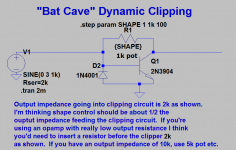
Dynamic Clipping Using a Transistor for Guitar Distortion
Hi all, thought I'd share this circuit
and get any feedback you want to offer.
In electra type distortions, there
are 2 diodes going to ground at the output to clip
the signal. I got the idea to use a transistor
to clip the signal, but let the signal also perturb
the transistor through the base and when the signal
is high to allow the top of the wave to depress
and go towards ground from collector to emitter.
In other words the signal itself changes the clip.
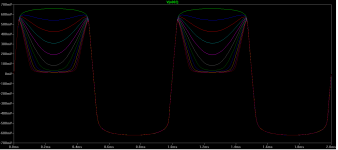
There is a shape control resistor when raised,
causes the voltage at the base to increase and the
top of the signal caves downward.
I haven't seen this done before so I thought I'd
share it.
Hi all, thought I'd share this circuit
and get any feedback you want to offer.
In electra type distortions, there
are 2 diodes going to ground at the output to clip
the signal. I got the idea to use a transistor
to clip the signal, but let the signal also perturb
the transistor through the base and when the signal
is high to allow the top of the wave to depress
and go towards ground from collector to emitter.
In other words the signal itself changes the clip.
There is a shape control resistor when raised,
causes the voltage at the base to increase and the
top of the signal caves downward.
I haven't seen this done before so I thought I'd
share it.
Attachments
Last edited:
Why not build it and see how it sounds? Usually extremely "pointy" waveforms like that sound extremely harsh and unpleasant.
By the way, 1N4001 diodes are quite slow, and not well suited to rectifying audio signals. A 1N4148 will do a much more accurate job; whether that means it will sound better, worse, or the same, I cannot say.
-Gnobuddy
By the way, 1N4001 diodes are quite slow, and not well suited to rectifying audio signals. A 1N4148 will do a much more accurate job; whether that means it will sound better, worse, or the same, I cannot say.
-Gnobuddy
Yes that pointiness I think may sound thin. Because in part of the audio has the frequency doubled too. But that's where the shape control comes in I suppose I was thinking you could vary by ear as a distortion shape control. I need to give it a whirl and get back to you after I do. I was travelling and just got back so I'll have to build something and let you know. Thanks for looking!
I use a soft limiter as most guitar distortion pedals are too harsh.
An externally hosted image should be here but it was not working when we last tested it.
"Tested"
Thank you nigel, that is a really cool circuit in your feedback loop. Nifty! I'm going to experiment with that a bit.
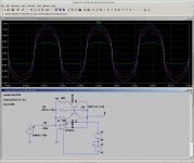
I tried my pocket oscilloscope out for the first time and tried a circuit. I hooked up this at the output of a little class A amp that had a midrange band pass filter on it. The most I can say at this time is it works. It basically sounded like a high midrange hard rock or metal type distortion that thinned out with the control. It had too much midrange, but some of that was coming from the bandpass I think.
What I really need to do is build a little electra type distortion which I think may end up with a little more bass than the amp I had, maybe a jfet buffer, then into a tweaked marshall type tonestack with obligatory midrange cut. I think that filtering will help a lot and bass boost. Want to try the 4148 also instead of the 4001 also.
Thank you nigel, that is a really cool circuit in your feedback loop. Nifty! I'm going to experiment with that a bit.
I tried my pocket oscilloscope out for the first time and tried a circuit. I hooked up this at the output of a little class A amp that had a midrange band pass filter on it. The most I can say at this time is it works. It basically sounded like a high midrange hard rock or metal type distortion that thinned out with the control. It had too much midrange, but some of that was coming from the bandpass I think.
What I really need to do is build a little electra type distortion which I think may end up with a little more bass than the amp I had, maybe a jfet buffer, then into a tweaked marshall type tonestack with obligatory midrange cut. I think that filtering will help a lot and bass boost. Want to try the 4148 also instead of the 4001 also.
Attachments
What fun! It's always nice when something you imagined actually works, and that too, works just the way LTSpice predicted it would work.It basically sounded like a high midrange hard rock or metal type distortion that thinned out with the control.
The 4148s will be faster and more accurate, but who knows, that may actually sound harsher. The slower 4001 may be adding a little lowpass filtering to the sound, and smoothing it out a bit.Want to try the 4148 also instead of the 4001 also.
Once again, I think a quick trial on a breadboard is the way to go. A few minutes listening will tell you all you need to know!
This is the sort of analog circuit I still enjoy - creative, non-textbook stuff that uses the non-linear, imperfect nature of the devices themselves, and turns that into something you can make music with. Very cool!
-Gnobuddy
Thanks for sharing that very interesting circuit!I use a soft limiter as most guitar distortion pedals are too harsh.
I assume you use some sort of gain/buffer between the guitar and this circuit?
I drew up your circuit in LTSpice (using similar components and a dual rail supply) and did a little virtual experimenting. LTSpice thinks that using a 470k pot instead of a 2.2M one will make the distortion control's action smoother (more uniform over the pot's travel). The attached image assumes 1 volt (peak) input signal at 700 Hz.
-Gnobuddy
Attachments
Thanks for sharing that very interesting circuit!
I assume you use some sort of gain/buffer between the guitar and this circuit?
-Gnobuddy
Yes I add quite a bit of gain before the soft limiter.
I also added a presence control after it to lift the treble for lead guitar.
Its a very old circuit, I found it in Wireless World in the 1980's.
It was a readers circuit.
You can get quite a few different sounds from it depending on where the pot is set. You can get quite a clean sound with the pot in middle. At either end of the pot it is more distorted with some compression.
Its a bit small but you can just about see what I have done.
An externally hosted image should be here but it was not working when we last tested it.
Thanks again! 🙂Its a bit small but you can just about see what I have done.
I can't make out the resistance values, but yes, I can see what you've done. Two gain stages before the controlled distortion stage, and an active Baxandall tone control after. Excellent!
-Gnobuddy
NOT the best distortion, but perhaps the simplest.
I'm just fooling around trying to find the simplest possible distortion circuit, and I came up with this. Thought I'd post it and move on to another project. (Of course there is the "Black Ice" type distortion which is passive distortion with Schottky diodes, but it simply doesn't work if your pickups aren't hot enough).
This circuit sets the transistor next to the bottom rail and it clips at around .7v and the other rail is set by the power supply, which is only 1.5 volts (Must use 1.5v battery or supply).
Attachments
"Softer" Version with second "shape" control.
I got a softer looking form with raising the clipping threshold with a 1k pot, but of course it gets louder, so I put another clipping pair afterwards. I used a 4148 and 2 1n34 to limit clip and then vice versa. Looks like it would help it not sound so harsh, but will just build and listen🙂
I got a softer looking form with raising the clipping threshold with a 1k pot, but of course it gets louder, so I put another clipping pair afterwards. I used a 4148 and 2 1n34 to limit clip and then vice versa. Looks like it would help it not sound so harsh, but will just build and listen🙂
Attachments

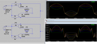
Another variation with a 2n3904 and 2n3906
Hi, I looked at Nigel's circuit and sort of played around without, looking for something to put after amplification, not in the feedback loop. This is what I came up with. 1st shape control is whether or not top of wave is concave or convex, 2nd control controls the bottom part of wave. I think you could also put 2 more pots to get a crown like shape, not sure what that would sound like. But I cannot model more than 3 parameters at a time in ltspice, so 4 shape controls are hard to model.
Hi, I looked at Nigel's circuit and sort of played around without, looking for something to put after amplification, not in the feedback loop. This is what I came up with. 1st shape control is whether or not top of wave is concave or convex, 2nd control controls the bottom part of wave. I think you could also put 2 more pots to get a crown like shape, not sure what that would sound like. But I cannot model more than 3 parameters at a time in ltspice, so 4 shape controls are hard to model.
Attachments
Going to build this and give it a try, 6 shape controls
I'm going to hook my oscilloscope up and watch the waveforms and listen as I tweak these 6 controls. I doubt I would need all 6 controls and some will likely get combined, but I'm going to try and figure out which forms if any sound pleasing/ok and then simplify this circuit a little. It'll probably just be the soft clipped ones, but maybe one of these asymmetric forms may sound good. Anyhow thought I'd share this one I came up.
I'm going to hook my oscilloscope up and watch the waveforms and listen as I tweak these 6 controls. I doubt I would need all 6 controls and some will likely get combined, but I'm going to try and figure out which forms if any sound pleasing/ok and then simplify this circuit a little. It'll probably just be the soft clipped ones, but maybe one of these asymmetric forms may sound good. Anyhow thought I'd share this one I came up.
Attachments
Is asymmetric clipping in distortion ok for your amp?
Hi all, this is a basic question. I've been building guitar distortion circuits. Some that I've come up with have say negative peaks at 200mv and positive peaks at 600mv. Is this bad to run into an amp? I'm assuming its better to center around zero. What is the common thought on this?
Hi all, this is a basic question. I've been building guitar distortion circuits. Some that I've come up with have say negative peaks at 200mv and positive peaks at 600mv. Is this bad to run into an amp? I'm assuming its better to center around zero. What is the common thought on this?
with reasonable high pass, likely already in place everywhere in musical instrument amp signal chains
but some home audio amps have very low, subsonic corner frequency and asymmetric clipping effect could push the woofer way off center for longish periods
but some home audio amps have very low, subsonic corner frequency and asymmetric clipping effect could push the woofer way off center for longish periods
A guitar signal can be very oddly shaped.
I would be applying a sine wave from a generator and checking the circuit is OK.
I would be applying a sine wave from a generator and checking the circuit is OK.
Hi,
Asymmetry in the distortion circuit is need for even order harmonics. Its fine.
rgds, sreten.
Asymmetry in the distortion circuit is need for even order harmonics. Its fine.
rgds, sreten.
- Status
- Not open for further replies.
- Home
- Live Sound
- Instruments and Amps
- Simple 2 transistor panel mount guitar preamp.