Yes djk, there is a dual 10 amp output relay and not too bad, even if only a generic Chinese copy. Maybe a tap on its case with the screwdriver handle to see what those contact gremlins sound like when they become a problem? 😀
Oscillation when exiting clipping
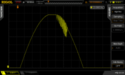
Was going to start a new thread but forgot I had l aready posted in this one. Anyhoo.. i was feeling a bit bored with being cooped up in the house so I attached a function generator to the amp and scope to the output, both of which I didn't have when I built the amp, and connected an 8 ohm resistive load. Drove it with a 1kHz single cycle tone burst every 50mS to check max output. managed 49 volts peak at the onset of clipping, but as it comes out of clipping, even if only clipping *very* slightly, there is a burst of oscillation. Screenshot is offset below bottom of screen. I'm a but surprised at this - I would have thought that this kind of thing would have long been sorted out before the design was published. so, what might be the cure for it? Amp details in link.
https://www.google.com.au/url?sa=t&rct=j&q=&esrc=s&source=web&cd=1&ved=2ahUKEwjE0d3Gyb3pAhXmxjgGHZfyBpEQFjAAegQIAxAB&url=https%3A%2F%2Fdownload.altronics.com.au%2Ffiles%2Finstructions_K5155.pdf&usg=AOvVaw209H2b6FiB4T8anh-U7UYY
Attachments
There have been several versions and more than one designer working on "Ultra Low Distortion Audio Amplifier" projects at Silicon Chip. IIRC, The current editor, Nicholas Vinen, designed at least the last 3 and you can be sure he would have looked at previous models and found such a problem if it existed, then fixed or avoided it one way or another, in his versions.
It looks like yours is the second version, as sold in a kit form by Altronics, according to the pic in post #11. There was, I recall, some comment on the design after it was published, which showed there was higher distortion when the speaker spade terminals were attached to the board with plated steel bolts and nuts. Brass bolts were no problem, plain or plated but they were talking of a typical differences like only 0.002% versus 0.004%. Anyway, the assembly method was unconventional and I think it remained a bit dodgy.
Silicon Chip were using a virtually new AP-2 distortion analyser for their tests then and you can bet the editor was testing everything imaginable with the new toy, nearly 20 years ago now. 'could be they didn't consider this type of single-cycle burst testing though.
Why not email the current editor, Nicholas Vinen, with the query, including your particular version detail? He took up the further development of the series to the present day when he joined the staff at Silicon Chip and it's quite likely he is familiar with any problems with earlier versions like yours by Leo Simpson, I understand.
See here for some info that might help you Fast Voltage Amplifier Stages for Audio Power Amplifiers
The oscillatory behavior you see often happens in amplifiers when driven into clipping.
The amplifier schematic shows no clamping on either Q8 or Q9 or indeed across the current mirror collectors
The oscillatory behavior you see often happens in amplifiers when driven into clipping.
The amplifier schematic shows no clamping on either Q8 or Q9 or indeed across the current mirror collectors
Last edited:
That's interesting. Looks similar in principle to stopping a servo amplifier winding up when an actuator position is maxed out. Why don't all good amplifiers have those diodes? So simple and cheap.
The diodes are the cheap s d easy way to do it - Ostripper and dadod showed slightly more sophisticated techniques.
Another point is that in amplifiers that use heavy compensation (like the ULD amp at 100pF) and fast VAS stages, they are more likely to oscillate coming out of hard clipping than if they were more sympathetically compensated - just an observation from playing with this stuff.
Of course, using slow devices like MJE340/350 also leads to serious rail sticking (and distortion) and this type of parasitic oscillation.
The diodes are the cheap s d easy way to do it - Ostripper and dadod showed slightly more sophisticated techniques.
Another point is that in amplifiers that use heavy compensation (like the ULD amp at 100pF) and fast VAS stages, they are more likely to oscillate coming out of hard clipping than if they were more sympathetically compensated - just an observation from playing with this stuff.
Of course, using slow devices like MJE340/350 also leads to serious rail sticking (and distortion) and this type of parasitic oscillation.
Just to add that this diode should be with very low reverse polarized junction capacitance, to prevent to high increase of HF THD.
- Home
- Amplifiers
- Solid State
- Silicon Chip ULD amp