Output board need extra DC5v power supply.Hi Paul, have you tried play BBB (with Pure-Botic) & PPY-recklocker & digital output board also with TOSLINK, SPDIF, AES / EBU or just with I2S output ?
I tried to connect a CD player that has SPDIF and TOSLINK inputs from 44.1 to 192 kHz (16 to 24 bits) with such combination but DAC in CD player
does not recognize any signal.
PPY-recklocker is original (not modified), I try with UPNP and NAA (hqplayer) protocols, Pure version is from 06.12.2020.
Also, I believe that Pure must be set in I2S mode and not in USB or SPDF ?
NB When I use I2S DSC2 DAC, everything works perfectly but only when streaming is DSD signal, of course.
Dear Nautibuoy and Jesper,The oscillators are available from Audiophonics
https://www.audiophonics.fr/en/comp...584-ultra-low-jitter-clock-45mhz-p-14033.html
and the ICs are available from the normal places like Digikey, Mouser or, if you're in the EU, Time but seem to be victims of the global shortage of silicon - maybe check ebay for a local small supplier but expect to pay an inflated price and be less confident about provenance.
thank you very much!
Thanks for your advice, I realize that, unfortunately, we are in the middle of a big mess and, unfortunately, it seems that nobody has what I am looking for.
I have tried to find alternatives with the tools provided by Mouser, but without success. Does anyone know alternatives to the ICs that I need to close this project?
Hi Paul, I know that I2S_1 / I2S_2 jumper must be in position I2S_1. But do the 2 jumpers (red circle in the attached image) have to be shorted or free for our configuration ?Output board need extra DC5v power supply.
Attachments
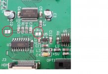
Hi all, just to let you know that everything works great, there seems to be some problem at 44.1 and 48 kHz, I'll analyze that along the way. In the next phase I will connect this same CD player directly via I2S to run at 384 kHz (now plays great with 24/192).Hi Paul, I know that I2S_1 / I2S_2 jumper must be in position I2S_1. But do the 2 jumpers (red circle in the attached image) have to be shorted or free for our configuration ?
Attachments
Hi Paul,I have PCB and gerber files(power supply,master clock & iso board) , but excluded output board , because it purchase from internet from china .
If you need ,please let me know .
I really like your project, do you still have PCB boards ? If not, can you attach gerber files ?
Hi Paul, I would like to ask you for an explanation, why did you use ACCUSILICON AS318-B-451584 for the Crystal Clock Oscillator instead of NZ2520SDA which is in the original scheme for ppy reclocker?I completed PPY's BBB player, I mod circuit diagram & PCB layout ,added master clock selector / power supply board and spdif / optical & IIS over HDMI socket output board ,two clock selected by buffer IC and enable when need, clock using DIP14 socket , all reg. IC upgraded to LT3045. Using PPY's pure firmware. Thanks for PPY.
View attachment 1044763View attachment 1044764View attachment 1044766View attachment 1044763
After a very long time, I'm finally getting back to this project, to build a DSC2
Just placed a Mouser order for most of the stuff, and also some connectors from proto advantage. Had to substitute a few ICs because couldn't find the potato semi stuff, but I think I found suitable replacements.
Be a good test for my newish hot air gun, will see if I can use it properly to put this together.
Randy
Had to substitute a few ICs because couldn't find the potato semi stuff, but I think I found suitable replacements.
There is a version without Potato on my page.
Thanks. Saw that, but I have a PWB for the potato version.There is a version without Potato on my page.
Renasas makes a 1:4 clock fanout chip, and onsemi makes a low skew clock buffer.
And they are pin compatible.
Randy
@ppy
I do have a question since you're here
On the DSC2 design,
J5-J8, pins 1&2, 3&4, etc are all shorted, which would short out the ladder resistors.
So I figured I have to cut all the traces between those pins. Then it looks like things will be connected correctly after I install the resistor boards.
Is that right? I don't see how it would work otherwise, but maybe I'm missing something.
Randy
There is no error in this. These pins are shorted to improve contact on critical weak signals.
Your mistake is that you think this DAC has an R2R ladder structure.
DSC2 is not R2R DAC.
Your mistake is that you think this DAC has an R2R ladder structure.
DSC2 is not R2R DAC.
Thanks for the info. Good thing I asked before screwing up my DSC2.There is no error in this. These pins are shorted to improve contact on critical weak signals.
Your mistake is that you think this DAC has an R2R ladder structure.
DSC2 is not R2R DAC.
Randy
@Paul9334
Dear Paul,
finally back to your project, I need some information that I can't find on my own but I need to finish the job.
The first thing are L1 and L2, in the list of components there are the same ones that Pavel uses in his project, but the space on your pcb is very small: which components did you use?
The second thing concerns the wiring of the switch (on off) and of the led, would you share the connection diagram with the bbb and the output card, so that I can reproduce it, because I can't find references on my own?
Also a curiosity: how is the on and off logic? How did you get the power supply disconnected from the mains?
Thanks for everything
Sergio
I assembled the DAC in the Beagle Bone version. For now, I only use with Amanero. I have a few questions. I temporarily installed E25 transformers, the target R3 is just coming to me. Can these transformers be optimally matched to the system? I know that despite the 10k:10k designation, these are completely different transformers. Next question. Are there 595 registers from modern production that can fully replace the old Philips or NXP ones. I can't find the old ones anywhere
Man I really want a DSC2 DAC but don't have the skills myself to build
Where can I buy one fully assembed ?
Where can I buy one fully assembed ?
Hi @ppy
Jussi (HQP) has mentioned:
Can you share details about what has been implemented in your DSC2 design?
An improvement over DSC1 ?
Thanks!
Jussi (HQP) has mentioned:
"make and model of the switch register-latches is pretty critical. Even if the model number is the same, different manufacturers have different implementations. Although they all work the same from digital data function point of view. However, this DAC use is a mixed-domain use case and very different from what the chip was originally designed for."
Can you share details about what has been implemented in your DSC2 design?
An improvement over DSC1 ?
Thanks!
- Home
- Source & Line
- Digital Line Level
- Signalyst DSC1