one more thing, how much of the "99.9% of music we listen to are recorded/mixed/produced using mundane resistors, IC's and (horror) electrolytic or even tantalum capacitors" (and signal thru dozens of these and many more so called horrors), sounds great. Recording engeneers even covet some of the oldest designs (Neve input modules from 75 still fetch >$2k, even with the horror, becuse they "sound great".
so you believe the charts are made with equal resistor temperature?
regards
They should be. And what exactly does nonlinear mean? Is it harmonic distortion? Do they show a test cct.?
Re: Re: size matters!
Which charts?
Juergen Knoop said:
so you believe the charts are made with equal resistor temperature?
regards
Which charts?
those posted by Martin in post #93
http://www.diyaudio.com/forums/showthread.php?postid=1597327#post1597327
I thought you were referring to the distortion vs. size issue.
I'm sorry, if I mixed it up. 😱
regards
http://www.diyaudio.com/forums/showthread.php?postid=1597327#post1597327
I thought you were referring to the distortion vs. size issue.
I'm sorry, if I mixed it up. 😱
regards
Ahh, thanks for clarifying. I didn't see the document surrounding those charts nor the test circuit, so I can't comment intelligently. But... I'd be highly surprised if ambient temperature was not constant.
My skepticism regarding thermal modulation is related to thermal mass and time constants.
My skepticism regarding thermal modulation is related to thermal mass and time constants.
hm, equal enviromental temperature doe not mean equal part temperature.
That's the usual trick...disclose as few information as possible and let the readers imagination work for you! 😀
Regarding voltage induced noise, I thought smaller resistors are better than larger ones.
So current density is not the decisive thing? 😕
regards
That's the usual trick...disclose as few information as possible and let the readers imagination work for you! 😀
Regarding voltage induced noise, I thought smaller resistors are better than larger ones.
So current density is not the decisive thing? 😕
regards
That's why you need the context- was this constant signal voltage? If so, what voltage was it?
Could you give me a cite or further detail on your statement that smaller resistors (physically smaller) have lower noise? How do you define "voltage induced noise"? Or did you mean Voltage coefficient of resistance?
Could you give me a cite or further detail on your statement that smaller resistors (physically smaller) have lower noise? How do you define "voltage induced noise"? Or did you mean Voltage coefficient of resistance?
the best I found quickly on the net. There must be an article in one of the old Elrads somewhere, but the search program can't find it.
With voltage induced noise, I meant the current noise induced by DC on the resistor.
In the chart it is normalized to the resistance and expressed as uV/V.
regards
With voltage induced noise, I meant the current noise induced by DC on the resistor.
In the chart it is normalized to the resistance and expressed as uV/V.
regards
Attachments
Sometime I want to try measuring resistor noise. My guess, based on the lack of published circuits, is that it's fairly difficult for modern resistors, especially metal film or foil or wire.
I have seen pretty obvious voltage coefficients on MOX resistors, and I'd want to measure the specific parts in question before using them in an audio application. The distortion of a simple voltage divider was visible on a scope, but I was applying several hundred volts to the thing.
I've also seen much higher noise levels in SMT thick film resistors used in an instrumentation application, compared to the same size SMT metal films. I'd hesitate to use anything but a metal film or foil or even wire technology in low level circuits, and can't see why one would bother with anything else even for high power circuits.
As for audibility, I hesitate to comment, though I do think I hear significant differences between different pots and networks used for level controls.
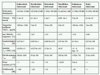
see page 14 of the document for some VCRs
http://www.bbs1-kl.de/fileadmin/user_upload/schulformen/hbfi/Datenblaetter/widerstand.pdf
http://www.bbs1-kl.de/fileadmin/user_upload/schulformen/hbfi/Datenblaetter/widerstand.pdf
Thanks, Juergen. It would appear, though, that what I meant by size (physical dimensions) and what you meant (resistance value) are different; it's the ambiguity of language.
Given changes in composition for different resistance ranges, differences in coating thickness, and different trim geometries for different resistance values, it's impossible to determine from that chart what the current densities actually are. Contrariwise, if I pick a constant value of resistance and compare excess noise (from whatever source) between different wattages (and hence different physical size), the larger one will tend to have the lowest excess noise.
Given changes in composition for different resistance ranges, differences in coating thickness, and different trim geometries for different resistance values, it's impossible to determine from that chart what the current densities actually are. Contrariwise, if I pick a constant value of resistance and compare excess noise (from whatever source) between different wattages (and hence different physical size), the larger one will tend to have the lowest excess noise.
VCR is already english and means voltage coefficient of resistance, if I'm right.
Meßspannung means measurement voltage.
regards
Meßspannung means measurement voltage.
regards
if I remember correctly, the old article states that the higher wattage 1-2W types had also higher current noise than their 1/4W-1/2W relatives.
This was true for both the carbon- and metalfilmfamily.
regards
This was true for both the carbon- and metalfilmfamily.
regards
CG said:
How can this possibly be? I've read over the past week on another thread here that people who played with audio circuits were naturally predisposed to always choose the most expensive parts as being the best sounding. It's apparently something in human nature.
So how can these bulk foil resistors not be by far the best?
Of course, that's ignoring the fact that all resistors must sound alike.
The ear hears by level..over time..and this becomes the 'apparent loudness' of the given transient component. So resistors with less self noise and less smear....will sound softer. But with more micro-information.
Noise AMPLIFIES presentation of the micro and transient information (anything with a high delta becomes smeared in time by the resistor noise) , and many, many, many, many designers and audiophiles make the mistake of thinking that 'greatly exposed' micro detail is occurring when in fact it is NOISE. Ie, ---not correct signal.
One must understand what the ear is looking for. Then we can evaluate what it is--that the components are doing.
Re: Re: Signal path Resistor Quality
About 6 months back, I bought a full replacement set of PRP's from Parts connexion to refit a MFA Magus C. I have yet to do the dirty deed. I'm'agonna get to it real soon. Can you describe the sound of the PRP's? Anything like the Holco's?
rdf said:
Hi rtate. Having fun yet? One recommendation is put a single toe in the water first. Try the PRPs available from Partsconnexion at ~$0.40 a pop. Some hate 'em, some love 'em (count me among the latter), neither is important. If PRPs make an audible difference in your circuit compared to off the shelf generics, for you it's worth chasing resistors. If it makes none, you'll have ventured little financially and gained a sense of style. PRPs look great.
About 6 months back, I bought a full replacement set of PRP's from Parts connexion to refit a MFA Magus C. I have yet to do the dirty deed. I'm'agonna get to it real soon. Can you describe the sound of the PRP's? Anything like the Holco's?
Upfront disclaimer: I almost entirely traded the iron for pedals at the beginning of the year and haven't revisited resistors in a while. That granted, the simple answer from memory is "no, and that's what I liked best about them". To my ear carbon comps are hashy in a facsimile of 'life' way, generic magnetic metal films hard with glare, cheap oxides just bland and lacking in detail or resolution. In my applications the PRP seemed better than the surrounding circuit and didn't leave a thumb print. They disappear better than Mills. At the price, what's to lose?
Long life to exotic resistors.
Then again, biasing is the only thing that remains when there is no audio signal at all 😀
Then again, biasing is the only thing that remains when there is no audio signal at all 😀
at least the metal films are low on distortion and noise.
Found an explanation for the A3 figure.
It's third harmonic distortion at a 10kHz fundamental.
The procedure is probably layed down in IEC 440.
regards
Found an explanation for the A3 figure.
It's third harmonic distortion at a 10kHz fundamental.
The procedure is probably layed down in IEC 440.
regards
Eva said:Then again, biasing is the only thing that remains when there is no audio signal at all 😀
In my more madcap and reckless moments I've even been know to set voltages, circuit loads and filter points with them. Wheeeeeeeee!
- Status
- Not open for further replies.
- Home
- Amplifiers
- Solid State
- Signal path Resistor Quality