When I first started trying various circuits in LTspice for a SiC common source amplifier, I was preoccupied with low distortion. Last night, I decided that it would be better to just try a simple circuit to get a handle on how the JFET performs in real life instead of chasing distortion in LTspice.
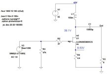
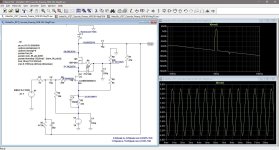
I did try a few scenarios in LTspice and settled on a simple choke loaded common source amp with source resistor self bias. The source resistors would not be bypassed and some local negative feedback would be present. A 42 volt power supply seemed to produce reasonable distortion numbers at 1 watt.
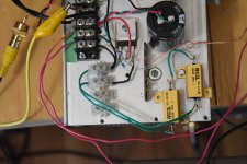
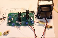
I couldn't go to bed without finding out how this circuit worked, so I reconfigured the source follower test amp to common source. The new circuit does not have a bias supply, so the circuit is simpler than the common drain amp.
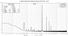
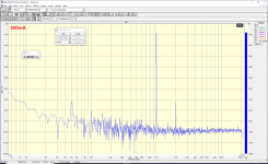
When everything was hooked up, I verified that it was indeed working and amplifying a signal. At that point, I had to do a quick distortion measurement, or I would definitely not get to sleep. After firing up REW, and fiddling around with the power supply voltage, I was pleased to see the amp put out 1 watt into 8 ohms with about 0.2% THD. Not super low distortion, but good for a single-ended common source amp.
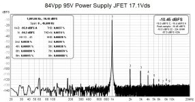
Today, I varied the power supply voltage without changing the 4.4 ohms of source resistance and found that the power supply of 42 volts produced the nicest balance of harmonics. I could get lower THD but the 3rd harmonic would start to dominate. With the 42 volt power supply, the operating point was 30.5 volt Vds at 1.9 amps.
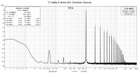
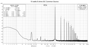
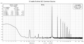
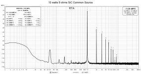
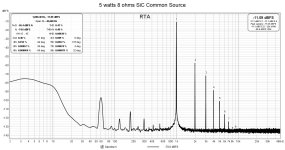
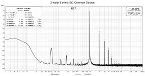
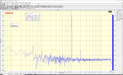
Total harmonic distortion reached about 1% at 12 watts into 8 ohms, 1.4% at 15 watts, and 2% at 17 watts. Gain is 1.8x.
For the 1 watt output distortion test, the signal source was my 1 kHz oscillator. For the subsequent higher power output tests, I used the prototype SiC preamp to boost the oscillator output to the power amplifier under test.
I did try a few scenarios in LTspice and settled on a simple choke loaded common source amp with source resistor self bias. The source resistors would not be bypassed and some local negative feedback would be present. A 42 volt power supply seemed to produce reasonable distortion numbers at 1 watt.
I couldn't go to bed without finding out how this circuit worked, so I reconfigured the source follower test amp to common source. The new circuit does not have a bias supply, so the circuit is simpler than the common drain amp.
When everything was hooked up, I verified that it was indeed working and amplifying a signal. At that point, I had to do a quick distortion measurement, or I would definitely not get to sleep. After firing up REW, and fiddling around with the power supply voltage, I was pleased to see the amp put out 1 watt into 8 ohms with about 0.2% THD. Not super low distortion, but good for a single-ended common source amp.
Today, I varied the power supply voltage without changing the 4.4 ohms of source resistance and found that the power supply of 42 volts produced the nicest balance of harmonics. I could get lower THD but the 3rd harmonic would start to dominate. With the 42 volt power supply, the operating point was 30.5 volt Vds at 1.9 amps.
Total harmonic distortion reached about 1% at 12 watts into 8 ohms, 1.4% at 15 watts, and 2% at 17 watts. Gain is 1.8x.
For the 1 watt output distortion test, the signal source was my 1 kHz oscillator. For the subsequent higher power output tests, I used the prototype SiC preamp to boost the oscillator output to the power amplifier under test.
Attachments

I've listened to the common source amplifier in conjunction with the preamp a bit over the last two days, and it has surprised me. When I started exploring the common source circuit, I did not expect much but I knew I had to check it out since I haven't seen any data on such a configuration.
After my power supply experience with the common drain source follower amp, I was pleased to see no such issues with the common source circuit. The current draw was well within the capabilities of my lab power supply and no current limiting was detected. This was true both during power output tests and during music playing sessions.
On first hearing music played through this preamp/amp combo, I felt that the sound was a bit fuller than with the source follower amp. Not a big difference, but more of a feeling. As I cranked up the volume and played some music with a heavier beat, I noticed the dynamic sound coming from the speaker. I had Madonna's Immaculate Collection on CD and the beat was thumping out hard. It was dance party time.
Next, I put on my Telarc CD, Ein Straussfest, which contains music played by Cincinnati Pops Orchestra conducted by Erich Kunzel. It contains waltzes, polkas, and marches complete with percussive sound effects. No problems reproducing the bangs and booms. I was not worried about blowing up my Altec compression driver, so the peak sound levels were right up there.
In the end, it's hard to compare different amplifiers listened to over different sessions, but one thing was sure. I enjoyed my listening sessions with the SiC preamp and common source power amp combination, more so than with the source follower amp. Today, I was listening to the amps for pure enjoyment.
The source follower was more picky about the power supply and I do not believe the power supply for the source follower prototype was adequate. So, this is probably not a fair comparison between the two amp topologies.
OveralI, I was impressed with the dynamics this common source amp in conjunction with the preamp could produce. The high efficiency speaker with horn loaded compression driver helps, of course. But there is definitely something about this particular SiC preamp / amp combo. I'm not usually this impressed by listening tests with my DIY amps with my test setup.
I am glad I tried this common source circuit and it is a simple one at that.
I've already got too many amps, but I want to build this SiC common source amp. For one, I only have one pair of common source amps, the BAF 2015 THF-15S monoblocks amongst several common drain designs, so it needs some company. This SiC design sucks a lot of power and will be heavy, so it will be a monoblock build as well.
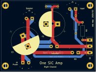
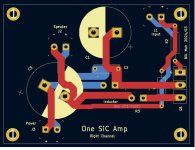
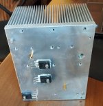
I put together a couple of PCB designs on KiCad, one for each channel. Very few parts, so the boards are small. The source resistors will be mounted on the heatsink, as they dissipate about 25 watts.
The SiC transistor dissipates about 70 watts, so with a combined heat load of about 100 watts, the Modushop 300 x 40 x 210 heatsinks should work for each channel. An Antek AS-3216 300VA 16V transformer wired in series will provide the power for each amp.
Attachments

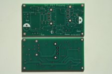
Over the last week or so, I've been coming back to the PCB layouts and making small changes that are hopefully improvements.
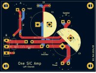
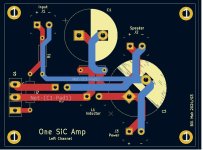
I wasn't happy with the input loop area of the right channel so that was changed to minimize it a bit more.
I moved the output bypass capacitor to shorten the traces to it. This will reduce the inductance and offer less impedance to the higher frequencies, which is what the bypass capacitor is supposed to do.
The last thing I did was to separate the returns to the ground point at the negative terminal of the decoupling capacitor. The idea was to reduce the interaction of the high return currents with the lower return currents, hopefully resulting in less noise.
I haven't designed many PCBs but I have been reading a lot lately about their layout, so I am trying to apply that information to my work. Hopefully, I've bottomed out on the Dunning - Kruger curve and am on the upswing.
Attachments
Indeed curious. It is not placed in the sick bin since a year? The trough of disappointment of that other 'learning curve'?
The adventure is alive and ongoing. In particular, the SiC preamp circuit is being used as the voltage amplifier in my 100 watt SIT follower amp project (https://www.diyaudio.com/community/...nt-resist-the-sirens-song.421505/post-7942974). I had circuit boards made and the design has been verified correct. This voltage amplifier stage was just what I needed to drive the SIT follower output stage to over 100 watts output into 8 ohms. Tests show that for 84V peak to peak 1 kHz output, THD is 0.0037%. I still intend to build this as a stand-alone preamp once I finish the 100 watt amplifier.
I intend to build the SiC follower amp as well. It will be perfect as another summer amplifier. I still need to design a PCB for it, though.
For now, I'm concentrating on finishing my 100 watt SIT amp, and then it's back to the SiCs. The SiC fever continues.
I intend to build the SiC follower amp as well. It will be perfect as another summer amplifier. I still need to design a PCB for it, though.
For now, I'm concentrating on finishing my 100 watt SIT amp, and then it's back to the SiCs. The SiC fever continues.
Attachments
What would be the latest SIC jfet preamp schematic? What would be the lowest rail voltages for this to work ok? Hammond choke is used for better PSRR or I could use some tube HV regulator for that? Then what would be the max rail voltages?
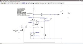
Attached is the schematic of the preamp that I am using as the voltage amplifier for my 100 watt SIT follower amp. It uses a -95V power supply. I have powered it with up to 125V to 130V power supply. Larger output swings with lower distortion comes with the higher power supply.
To get an idea of how the circuit would behave with a lower supply voltage, I ran simulations with LTspice and I have achieved reasonable results with a 36V power supply. The distortion is a little higher and the maximum output voltage is limited to somewhere over 20Vpeak-peak (10Vpeak) before distortion starts to increase rapidly. Still, at 8Vpp out, the THD is 0.0025% and at 20Vpp out, THD is 0.018%. So, with some adjustments to the cascode voltages and current, a wide range of supply voltages can be used. A negative or positve power supply can be used with minor changes. From my previous experience, LTspice has provided results with this circuit that are reasonably accurate. Certainly, the circuit is worth testing out.
The choke is the load for the cascode amplifier circuit. I started using chokes several years ago when I was modifying my Luminaria Sony VFET preamp. That's when I discovered that, like for tube amps, choke loading has several advantages. These include low distortion due to the high load impedance (flatter load line), high gain, and low voltage drop. A resistor load would have higher distortion and voltage drop, while a solid state CCS requires a much higher power supply voltage.
Also for transistor gain stages, the output impedance is quite low so cheap chokes work well, unlike with tubes.
For the 36V power supply LTspice simulation, I used the Hammond 156G choke. This is a smaller, cheaper choke than what I am using for my voltage stage in my SIT amp, but it shows what can be done. Simulations show flat frequency response through the whole frequency spectrum.
The circuits that I've shown uses negative power supplies since I'm powering the voltage amp with the output stage power supply which is positive ground (negative voltage out). No separate supply required for the voltage amp. However, a positive power supply version only entail some small changes
Attachments

Looks great. This is good for a SIT
[I used a folded circuit to achieve something like this, but mine is max 10mA as it has a parallel E88CC as input interface, also 36V Vb]
[I used a folded circuit to achieve something like this, but mine is max 10mA as it has a parallel E88CC as input interface, also 36V Vb]
- Can you share the .asc. - I have the UJ3N065080K3S model, but attaching that to a jfet symbol does not work - so rather ask a reliable source. ☕
@pinholer could you also please share the positive psu version? Is there a difference in performance between these two positive or negative psu? Do you have experience with another preamps that you could describe the sound from this SIC Jfet preamo? What would be the preamp consuption mA-s?
I have donut 2x16V and 1a. Maybe I can use this for that? For the negative psu I need quidence for that.
Could M1 be some other power mosfet?
I have donut 2x16V and 1a. Maybe I can use this for that? For the negative psu I need quidence for that.
Could M1 be some other power mosfet?
Here is the LTspice model that I usedLooks great. This is good for a SIT
[I used a folded circuit to achieve something like this, but mine is max 10mA as it has a parallel E88CC as input interface, also 36V Vb]
- Can you share the .asc. - I have the UJ3N065080K3S model, but attaching that to a jfet symbol does not work - so rather ask a reliable source. ☕
Attachments
I’m also thinking about building an amplifier based on UJ3N065080K3S. I have two of them. Previously, I assembled a circlotron using SiC. But SiC requires thermal compensation; when heated, their current increases. Now I'm looking for a suitable SE circuit. I like your work with SiC.
Attachments
Last edited:
I modified the circuit for a positive 36V power supply and made adjustments to the MOSFET biasing to match the negative power supply circuit values. This results in both circuits functioning identically. The current through the circuit is 36mA.@pinholer could you also please share the positive psu version? Is there a difference in performance between these two positive or negative psu? Do you have experience with another preamps that you could describe the sound from this SIC Jfet preamo? What would be the preamp consuption mA-s?
I have donut 2x16V and 1a. Maybe I can use this for that? For the negative psu I need quidence for that.
Could M1 be some other power mosfet?
You can series the toroid secondaries to get 32VAC and after rectification and filtering, will probably get 42V to 45V DC output. I recommend CLC filter for efficiency. Your toroid can power this preamp with no problems.
As indicated on the schematics, M1 is an IRFP240 MOSFET.
Soundwise, I have no complaints. I have a choke loaded Sony 2SK82 VFET preamp and I would not hesitate to use the SiC preamp instead. Still have to build a standalone version first, though.
Attachments
When I had my common source single-ended version of the amp prototyped, I listened to it for a period of time and I did not encounter any runaway current issues with temperature. However, it was source resistor biased so that would help prevent that problem.I’m also thinking about building an amplifier based on UJ3N065080K3S. I have two of them. Previously, I assembled a circlotron using SiC. But SiC requires thermal compensation; when heated, their current increases. Now I'm looking for a suitable SE circuit. I like your work with SiC.
I really liked that amp. It was simple and sounded good. The only downside was low gain, but that can be solved with a SiC preamp.
I got the least distortion in the circlotron with a quiescent current of 1A, but then I reduced the current to 0.5 A.
It would be good to measure the real volt-ampere characteristics of the UJ3N065080K3S
And then see where they have a good area to work.
How do they do it with tubes.
I will have the opportunity to make such measurements in about a week
Attached is an example of SIT measurement


And then see where they have a good area to work.
How do they do it with tubes.
I will have the opportunity to make such measurements in about a week
Attached is an example of SIT measurement
Last edited:
The dependence of the THD on the quiescent current. 1W/8R
Output transistors uj3n065080k3s.
Without thermal stabilization, the current rises slowly. When the cold amplifier is turned on at currents of 150 mA, 200 mA and 350 mA for three hours, an increase in the current is visible on the diagram.
If, when you turn on the amplifier with cold radiators, set the current to 150 mA, then the thermal sensor is not needed.
P.S. I would like to add that such parameters were obtained in the circlotron circuit without general feedback.
Attachments
Last edited:
- Home
- Amplifiers
- Pass Labs
- SiC Adventures - Exploring the UJ3N065080K3S