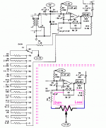
I'm looking at the schematic for a Shure FP11, a small battery powered mic pre:
Shure Publications | FP11
The gain control is a stepped series attenuator in the feedback loop of the first opamp, with an 84dB range in 6dB increments. Can anyone explain why R5-18, the series resistors, have the values they do? In order from R5 to R18:
1.33k (+78)
2.87k (+72)
6.65k (+66)
14.7k (+60)
15k (+54)
4.12k (+48)
1.33k (+42)
536 (+36)
237 (+30)
115 (+24)
54.9 (+18)
28 (+12)
14 (+6)
6.81 (+0)
The intervals don't make any sense to me---they rise and fall, with the highest value in the middle of the dial at +54. Any idea what I'm missing?
Thanks,
-Erik
Hi Erik,
The intervals don't seem to make any sense because of the logarithmic behavior of the circuit.
I hope this article can give you an answer: Logarithmic resistor ladder - Wikipedia
Good luck
The intervals don't seem to make any sense because of the logarithmic behavior of the circuit.
I hope this article can give you an answer: Logarithmic resistor ladder - Wikipedia
Good luck
Ah nevermind---you're right of course, brain fart. It's late and I can't tell the difference between a log and exponential curve. Thanks.
Erik,
I noticed that the gain switching network also attenuates the stage output level. I was intrigued enough to simulate it. The given R values are correct and the overall stage gain does indeed track with 6dB gain steps, quite accurately within about 0.2dB worst case.
Thanks for posting the schematic,
Simon
...Shure FP11 ...The intervals don't make any sense to me---they rise and fall, with the highest value in the middle...
It is a Gain AND Loss network.
The two ends of the resistor string do different things.
We sometimes see this in g-amps, which may need high gain and low. It is commonly implemented as a potentiometer. Common taper pots would not give a smooth taper over more than 30-40dB but that's ample for guitar. Shure not only wanted repeatable settings, they wanted 78dB of range, and the resistor string does that.
U2 is a (selected) LM386. R23 is surely 10r, not 10K.
Attachments
Cool, yeah---I was wondering why the other end was hooked up that way, was gonna be my next question. 🙂
Thanks all!
Thanks all!
One more question: What would be necessary to adapt this for use in another opamp circuit? Like, are there values (R4, R19, resistor string values, etc.) that are dependent on other values in the circuit, and would have to be changed? Or could you drop this on the feedback loop/output of most similar (noninverting amplifier-connected) opamps and get an 84dB attenuator?
One more question: What would be necessary to adapt this for use in another opamp circuit? Like, are there values (R4, R19, resistor string values, etc.) that are dependent on other values in the circuit, and would have to be changed?
The main feedback and attenuation resistors could be used in other circuits.
Don't forget R20, it's the upper half of the output attenuator. Because of R20, the output impedance is rather high so any following stage must be high impedance input or use a buffer. Also R3 is part of the feedback network.
erik said:Or could you drop this on the feedback loop/output of most similar (noninverting amplifier-connected) opamps and get an 84dB attenuator?
Yes, as above, but you won't get 84dB gain from this stage alone. The U1A stage has just under 30dB gain on its own.
The rest of the gain comes from:
- mic input transformer, 20dB
- Output amp U2, 26dB
- Line output transformer, about 10dB
There's some other small losses to bring the total down to 84dB.
Here's the sim file
Attachments
- Status
- Not open for further replies.
- Home
- Source & Line
- Analog Line Level
- Shure stepped attenuator: why these values?
