Hi guys,
Can anybody provide the original parts list for the Borbely "EB-906/255" All-Fet Shunt Regulator ?
Thanks.
Can anybody provide the original parts list for the Borbely "EB-906/255" All-Fet Shunt Regulator ?
Thanks.
Hi,
I found the reg schematic inside an Are Waagbo article.
But there is no BOM and the schematic has no values.
I do not have that reg in any of Borbely downloads.
I found the reg schematic inside an Are Waagbo article.
But there is no BOM and the schematic has no values.
I do not have that reg in any of Borbely downloads.
Yes, no parts list - almost all the parts are discontinued, if you can find them then we’ll talk about the resistors
Input 2sk389/2sj109 or matched pair 2SK170BL /2SJ74BL
Cascodes 2SK246/2SJ103 nice if you match pairs , but not necessary
Drivers 2SK982/2SJ148
Power devices 2SK2013/2SJ313 or for high power 2SK 1529/2SJ 200 and 2SK1530/2SJ201
E102 current sources
LM329 for vref , you can make quieter
Input 2sk389/2sj109 or matched pair 2SK170BL /2SJ74BL
Cascodes 2SK246/2SJ103 nice if you match pairs , but not necessary
Drivers 2SK982/2SJ148
Power devices 2SK2013/2SJ313 or for high power 2SK 1529/2SJ 200 and 2SK1530/2SJ201
E102 current sources
LM329 for vref , you can make quieter
Last edited:
Found the complete article in a russian forum :
http://forum.vegalab.ru/attachment.php?attachmentid=192287&d=1380107251
http://forum.vegalab.ru/attachment.php?attachmentid=192287&d=1380107251
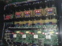
Maybe you can read the resistor values from the picture, maybe I have a list somewhere,
I changed LM329 Vref to LEDs
I can take more pictures so you can see all the resistors. There are 10 Borbely shunts in this balanced DAC , it uses Erno’s IV converters biased at 90 ma
Theres a 2 ma current source that got replaced with a 1.5 k resistor, but lafter I put in the original current souces and it worked OK
Attachments
Last edited:
I already have this article but it doesn’t show the components values.
This is true, but you can work it out yourself or with help of forum members.
As a start :
- your input voltage
- desired output voltage
- load current
..
The fets however will be hard to find and I recommend redrawing to bipolar.
These shunts seem component critical and may need a few mods to prevent oscillation. See this article in AudioXpress: Shunt or Not - Looking for the Ultimate Audio Voltage Regulator | audioXpress
In light of expense and difficult to obtain parts, maybe a Salas shunt would be easier?
In light of expense and difficult to obtain parts, maybe a Salas shunt would be easier?
These shunts seem component critical and may need a few mods to prevent oscillation. See this article in AudioXpress: Shunt or Not - Looking for the Ultimate Audio Voltage Regulator | audioXpress
In light of expense and difficult to obtain parts, maybe a Salas shunt would be easier?
The question remains the same : what are the passive components values of the schematics shown in Fig4 and Fig5 of this article?
Again : This depends on
- your input voltage
- desired output voltage
- load current
"Fig4 and Fig5" are Fig 6 and 7 in the print version.
- your input voltage
- desired output voltage
- load current
"Fig4 and Fig5" are Fig 6 and 7 in the print version.
Last edited:
Considering both the EB-906/255 and EB-806/273 :
- the input positive and negative shunt currents, adjusted respectively by R1 and R2, will set the allowable positive and negative load currents
- the desired positive and negative output voltages are adjusted respectively by P1 and P2
All the rest will remain the same. Do you know the values?
- the input positive and negative shunt currents, adjusted respectively by R1 and R2, will set the allowable positive and negative load currents
- the desired positive and negative output voltages are adjusted respectively by P1 and P2
All the rest will remain the same. Do you know the values?
Example: Simple Mosfet Shunt Regulator
It tested by my friends. Several of this design built and until now no problem found.
It tested by my friends. Several of this design built and until now no problem found.
See post 13
As you prefer...
For both positive and negative sections :
Vin:30V / Vout:24V / Iout:150mA
Mother told us to say "please".
However looking at your post 14 it seems you are able to figure it out yourself,
isn't it ?
Post 18 : this is nice, all required values are there. For 24 V replace Zener D1
(D5) with Z11 or Z12, for 150 mA maximum R1 in the current source is 4 Ω.
So choose R1 smaller according to shunt and regulator supply current.
Bimo, what is C3 (C17) good for ? Please explain.
- Home
- Amplifiers
- Power Supplies
- Shunt Regulator