Pleae quote exactly what it is?No offense, but your language consists of petty low-level nagging.
Please confirm that in practice with the SE (not toroid) transformer. If it itrue it wil clearly show the dif. on the transfer in low region.And yes, permeability changes with excitation level, so transfer characteristic will vary. If you deny this fact, I wouldn't be bragging on transformer knowledge if I were you.
One measurement with small signal anfd other with large.
Put the output tube in negative grid bias with grounded cathode, to eliminate impact of artificially boosting LF with wrong RC constant in catode, and use moderate C last to transformer...
cheers.
.
Last edited:
low permeability and standard power laminations window, are the main reasons for people always complaining to bass on SE ampsIt's a SE transformer, low permeability can be required. What's the big fuzz over 440 permeability?
🙁
It is simply very low value. Could not achieve correct value of L in primary. Even with a standard dim. of window for copper wire windings.
There is no use to increase the core area, because window remains the same. And has more damage to the transformer by increasing the wire lenght Rdc.
There are numerous examples of very big cores OT even without square core surface but it is not the soution.
.
Solution IS to use higher relative permeability cores of 800 or 1000. Correcting the magnetisation issues with calculated increased air gap,
And different geometry , with LARGER standard of window of windings space.
Then you can put larger amount of turns in primary, even larger diameter wire, decrease Rdc, lower induction in [T], better isolation, and so.
.
With standard "refrigirator" laminations of 200 to 450 relative permeability is always compromising and actually you could not made propper transformer...
Maybe for 2A3 in parallel only...

Pleae quote exactly what it is?
.
Especially this one. Seriously, do you think you're placed into a transformer competition or something? Is this supposed to be a bragging on achievements or something?
BTW i made some output transformers long before you aplied to this forum 😉
(Mine for 2A3 had -3db 8Hz/100Khz, but it winded on brand VAC cores for audio applications.)
Permeability is a tool value, not a ultimate parameter to reach for. You need low permeability in some SE transformers to avoid core saturation from Idc. I thought this would be basic knowledge to understand. If you start with a higher core permeability than needed for your SE application, you'lll need to airgap it anyway. A permeability of 440 is pretty fine for achieving 35H on a hypothetical transformer with 4000 primary turns, which is pretty fine for a 2A3 output transformer.
How do you come to the conclusion that low permeability alone results in low bass perception?
https://www.mennovanderveen.nl/images/onderzoek-ontwikkeling/publicaties/download_1.pdf
According to Menno van der Veen, cores for SE OPT's should have high permeability.
His AES lecture is about the behavior of the output transformer at SPL's at the treshold of our hearing, and his conclusion is that high permeability cores have enough permeability "left" in SE applications (airgapping) to have crucial benefits.
He compares a GOSS core with socalled annealed VM111 lams, and his conclusions confirm the advantage of using higher permeability cores.
This also happens to be my experience (just a pity that at the time, 2007, Menno apparently did not have access to higher permeability cores).
Nanocrystalline cores represent the SOTA wrt permeability for OPT application.
Avoiding core saturation from Idc is an other subject.
Last edited:
Small signal means 1 mW not 1W.No that is not true...
IF somehow magicaly it is true then the amplifier will have dramaticaly different transfer in the low end with 1W and 10W power...
BUT IT IS NOT THE CASE
You can easily prove to yourself by measure the device with small signal input and large one.
.
BTW i made some output transformers long before you aplied to this forum 😉
(Mine for 2A3 had -3db 8Hz/100Khz, but it winded on brand VAC cores for audio applications.)
.
Please check the [units] in your formulas they shoud be compatiobile, same from each sides of equations...
If I have 26H for 1 mW and 34H for 1W, the frequency response with 300B will be 3 dB down at 4Hz and 3Hz, respectively. L will keep increasing but not as much until max Pout.
Last edited:
Because he is using toroidals with fancier material. For the same material, usually toroidals have higher permeability than C cores and loose laminations.https://www.mennovanderveen.nl/images/onderzoek-ontwikkeling/publicaties/download_1.pdf
According to Menno van der Veen, cores for SE OPT's should have high permeability.
Then if you want to use a large core with tiny gap and want small core loss at the same time need to use fancy materials.
From my perspective this is mirror climbing race. For few Hertz it is not a must, especially because of the ACTUAL use. If I happen to get one fancy core I will certainly use it, if I don't I sleep well anyway.....
Good transformer design and making is 95% something else.
Last edited:
Are you sure about Menno's toroidals with what you call fancier materials?
In the past on several occasions I tried to have a conversation with Menno on core materials but he has always been very reluctant to exchange ideas (not so with Per Lundahl; discussing with Per has always been a joy, and now he also has some amorphous and nanocrystalline stuff).
I am pretty sure Menno's toroidals are 0.35 mm stock quality; how airgapping is applied for the SE OPT's I don't know. Menno has been more into tube schematics and designing transformers (winding schemes - calculation of parameters) than into core materials.
Funny that you continue to talk about "fancy" core material; amorphous and nanocrystalline cores are quite normal today. Tamura has amorphous core transformers; Monolith Magnetics has HiB GOSS, amorphous and nanocrystalline transformers. And Lundahl as already mentioned. Actually you can call EI M6 "prehistoric" when discussing quality transformers, good for 'middle-of-the-road" transformers but not for the best quality.
Good transformer making is combining design, best materials and experience.
As with many things in life it's about making choices.
Last edited:
I am fine with prehistoric, just like tubes are! Get over it you will never convince me otherwise, in fact I have much more important choices to make in my life than worrying about core materials that only bring questionable upgrades.
Last edited:
Yes it is, you are wrong. permeability and target minimum L of primary...Especially this one. Seriously, do you think you're placed into a transformer competition or something? Is this supposed to be a bragging on achievements or something?
Permeability is a tool value, not a ultimate parameter to reach for. You need low permeability in some SE transformers to avoid core saturation from Idc. I thought this would be basic knowledge to understand. If you start with a higher core permeability than needed for your SE application, you'lll need to airgap it anyway. A permeability of 440 is pretty fine for achieving 35H on a hypothetical transformer with 4000 primary turns, which is pretty fine for a 2A3 output transformer.
How do you come to the conclusion that low permeability alone results in low bass perception?
this is the main factor. Target is medium permeability NOT high permeability with transformers with larger magnetizatoin current.
second major is window size.
etc ets.
.
With 4000 turns Rdc of the primary can be wey low.
Small signal does nothing with Watts IN this case. We want from you to demonstate in practice claims about the change in inductaces caoused by change in permeability within the size of p-p signal at the primary.Small signal means 1 mW not 1W.
If I have 26H for 1 mW and 34H for 1W, the frequency response with 300B will be 3 dB down at 4Hz and 3Hz, respectively. L will keep increasing but not as much until max Pout.
So it will be the change in the grid (input) of power tube that is matters. say 90V p-p as largest input signal and 1V p-p as small
that will be enough...
just 2 measurements...
This is 5 star question 😎 really...How do you come to the conclusion that low permeability alone results in low bass perception?
.....
Because: relative permeability is much more increasing the inductance
more than insanely number of turns. You increasing the number of turns only to maintain inductance below 1 [T]. or better sqrt(2)/2 [T]
and with wire dia of density of 2A/cm2 (not 2.55)...
.
And more than irrationally increasing the core area, deforming the square ratio of area of the core.
with increasing one side of core adding more laminatons, You increase 1 winding lenght for 2 added value.
say that we ad just 1cm of lamination at the 4 x 4 cm core that will add 2 cm per turn. for 4000 turns You added 8000cm=80m cca of additional wire just for primarry...
And still with minor gain in inductace for that additional core area...
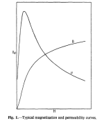
Guys, don't forget, we are talking about SE OPT which is per say biased with the DC, so even with the small signal, the core is in the middle of the magnetization curve. Correct me if I am wrong.
Thank you,
Andre
Thank you,
Andre
Zoran, I said 1 mW output power. That is quite precise. No guessing about....Small signal does nothing with Watts IN this case. We want from you to demonstate in practice claims about the change in inductaces caoused by change in permeability within the size of p-p signal at the primary.
So it will be the change in the grid (input) of power tube that is matters. say 90V p-p as largest input signal and 1V p-p as small
that will be enough...
just 2 measurements...
I have put down a design with all practical details so everyone can make the transformer and see. I also thought about it in a way that it can be tweaked with small changes to adapt to different situations, like for example more Idc current with slightly bigger air-gap.
I do not owe you anything. You can make the transformer yourself with your super-duper audio core and see. Can you? Or are you just bluffing???
👍Guys, don't forget, we are talking about SE OPT which is per say biased with the DC, so even with the small signal, the core is in the middle of the magnetization curve. Correct me if I am wrong.
We are going to see here the Schrodinger equation for SE transformers pretty soon 🙂
Taking into account size and output power, they are GOSS. May be M3 may be M4. May be 0.35mm, may be 0.27. After all it doesn't matter much. Winding layout design is what matters most. Air-gapping toroidal cores is not a big problem for today.In the past on several occasions I tried to have a conversation with Menno on core materials but he has always been very reluctant to exchange ideas (not so with Per Lundahl; discussing with Per has always been a joy, and now he also has some amorphous and nanocrystalline stuff).
I am pretty sure Menno's toroidals are 0.35 mm stock quality; how airgapping is applied for the SE OPT's I don't know.
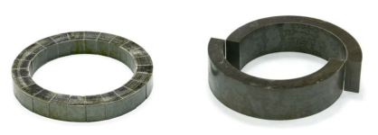
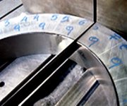
Attachments


I would rather see something more down to earth🤔.We are going to see here the Schrodinger equation for SE transformers pretty soon 🙂
Is there anyone who has experience with modern core materials as nano, amorphous and such? Any different technics in windings using those cores?
Thank you all,
Andre.
- Home
- Amplifiers
- Tubes / Valves
- Show your transformer work (gallery)