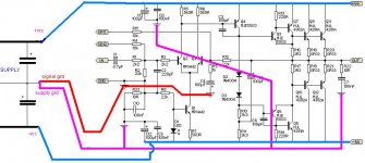
Yes that should be good. Remember the speaker ground returns to the star point as well, not the PCB. Signal input leads to the PCB should be insulated from the chassis.
Ground from snubber ( Boucherot ) you must lead separately, not by common wire with filtration...
bocka said:Hi,
its better to connect the GND from C12 directly to C13. You can also omit R23 and C10.
Yep, i can confirm that !
Mike
MikeB said:Yep, i can confirm that ! Mike
I only meant c12/c13, r23 can be necessary but if it is, it should not be bypassed with c10.
And if r23 is used, this signal gnd should not be further connected to the power gnd.
Mike
Hi Leander
With only two diode drops ( D2 an D3 ) you will have severe crossover distortion. You must add one or two more diodes and a trimmer pot for adjustment .
With only two diode drops ( D2 an D3 ) you will have severe crossover distortion. You must add one or two more diodes and a trimmer pot for adjustment .
Jorge, that's a CFP outputstage, it does not that high voltage to have bias ! With 4 diodes it will fry. But you're right, it's ClassB, and rod designed that thing for subwoofer.
Mike
Mike
Good Day,
Is it fine to connect the entire circuit common(star point ground) to earth ground of the power cable?
Is it fine to connect the entire circuit common(star point ground) to earth ground of the power cable?
MikeB said:Jorge, that's a CFP outputstage, it does not that high voltage to have bias ! With 4 diodes it will fry. But you're right, it's ClassB, and rod designed that thing for subwoofer.
Mike
Why not use a Vbe multiplier in place of D2, D3? However, the feedback pair bias stability may be an issue if biased AB.
Fantastic! Thank you Mr. Richie. If not, i would have to insulate the RCA input jacks(they are a fully metal type which is chassis mounted) and make the holes for them bigger, which means more work. Thank you!
You should insulate the sockets if you can. The idea with grounds is that you have just point/star grounds. If you use the whole chassis as ground you get loop currents called eddy current circulating around which causes small errors. This may not be a problem for you this time but it could be another time.
Does that amplifier circuit work ?? Im just a bit worried if
one does not buy the pcb from the author theres always issues that will arise..
🙂
one does not buy the pcb from the author theres always issues that will arise..
🙂
so u saying you did not buy a pcb from rod, u made one or trying to make one for ur self ? And u tested the amp it before attemping to make a pcb ?
😕
😕
Reactance said:so u saying you did not buy a pcb from rod, u made one or trying to make one for ur self ? And u tested the amp it before attemping to make a pcb ?
😕
I made one for myself andi it works great
MikeB said:Jorge, that's a CFP outputstage
Are you sure about that Mike? It looks to me like an EF stage, using Sziklai connected transistors as drivers. The design results in a high current for the driver stage, not sure what the purpose of that is?
Actually its a CFP driver stage and it isolates the driver thermal variations from the bias chain. As such drivers have a large variation in demand current supplying output transistor/load needs, it's a good idea. I used this in the Magnet 300F - which won the 'golden ear'!
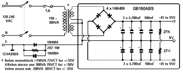
Regarding grounding, the chassis should be connected to incoming power (mains) ground and circuit ground connected to it (from the star point) via a low value resistor with back to back power diodes. This helps prevent ground loops when other equipment (of unknown method) is connected.
Cheers,
Greg
Regarding grounding, the chassis should be connected to incoming power (mains) ground and circuit ground connected to it (from the star point) via a low value resistor with back to back power diodes. This helps prevent ground loops when other equipment (of unknown method) is connected.
Cheers,
Greg
Attachments
- Status
- Not open for further replies.
- Home
- Amplifiers
- Solid State
- Should grounds go like this?