It uses single channel (mono) as original. It is the JFET part that might not be best suited for this circuit?
You may have to alter the in and out impedance, use presets till you get it right. Then change to fixed resistors.
Like I said, lots of work.
The original 5534 should be available, I don't think those are rare.
The other members, please give your opinion, suppose 5534 is not available, then what?
Like I said, lots of work.
The original 5534 should be available, I don't think those are rare.
The other members, please give your opinion, suppose 5534 is not available, then what?
The original is a single op amp, not a dual. What I don’t know about is compensation on the original. According to the schematic it has compensation pins and a cap. The 071 is internally compensated or unity gain, the 5534 isn’t. If the 5534 is used, the cap on pins 1 and 8 may need adjustment, but at least it gives you the opportunity to do it. Inside the overall feedback, the op amp drives a CFA with a gain of about 18. In this kind of configuration, an internally compensated op amp like the 071 usually works with no problems. The 5534 could be made to work as well, but might require tweaking. The 5534 will have an easier time driving the 1.2k input impedance of the CFA and may be a better choice for that reason.
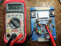
So the way that pot is in the circuit, it can be dialed to 0 ohms. With the 1K resistor downstream, 1K was the lowest setting possible. This overshot the bias voltage. With the 562 ohm resistor, and the pot at 65 ohms, its additive resistance measures 560 ohms in circuit. This was not possible to obtain with the 1K resistor. I guess a 470 ohm resistor would make better use of the trimpot.Something here does not add up. You SHOULD be able to set the pot to 232 ohms (or somewhere close) with the original 1k and get the very same result. It is about the right number of Vbe’s so the pot setting makes sense. Does that 1k resistor actually measure 1k or did it get damaged and go high?
Attachments
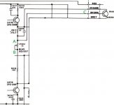
It looks to me like the brown wire is on the wrong side of the trim pot. If you have the 562 + 65 ohm pot in the collector-base, and the 150 ohm in the emitter base, it would behave like this. According to the schematic, the 562 (or 1k originally) should be in the collector-base by itself, and the pot+150 in the emitter-base. Then you would have a more comfortable range of adjustment. AND if the pot ever fails wiper-open (what happens when they get old and crusty) the bias will automatically drop, rather than rise to crazy levels.
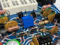
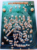
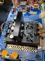
Here is a better picture of how the pot and the two resistors are wired. 562 ohm resistor on the left, pot, then 150 ohm resistor (tan) on the right. Notice 1 trimpot leg with the 562 ohm resistor and the other 2 legs with the 150 ohm resistor.It looks to me like the brown wire is on the wrong side of the trim pot. If you have the 562 + 65 ohm pot in the collector-base, and the 150 ohm in the emitter base, it would behave like this. According to the schematic, the 562 (or 1k originally) should be in the collector-base by itself, and the pot+150 in the emitter-base. Then you would have a more comfortable range of adjustment. AND if the pot ever fails wiper-open (what happens when they get old and crusty) the bias will automatically drop, rather than rise to crazy levels.
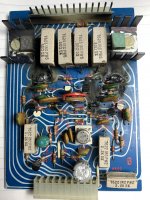
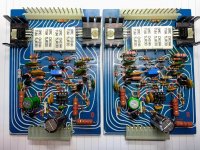
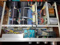
Tonight's progress, other board completed and tested. Less drifting on this board, and this is the one that burnt. Tested with the same power pack, too tired to pack the other heat sink, and they are hefty. 1.8 mV easily obtained. Great sound.
Attachments
The reflections on that back side picture make it hard to trace - you’ll have better luck with the PCB in your hand. The results you describe are as if C (brown wire) was connected at point B. The schematic shows it connected at point A. Point A is technically correct - as it easily allows the bias to be adjusted WAY down, and if the pot goes to maximum resistance this is what happens. With it connected at point B the adjustment is tricky - and if the wiper opened up on the original pot, it may have even been what caused the original failure. This wouldn’t be the first time a design error was overlooked, as it could be made to work.
If you just leave it, it will probably be “ok”, as that Bourns pot is about as good and reliable of one as you will get. I would be inclined to do one of two things. Either move the connection to where it is supposed to be, or change the pot out with a 100 ohm to limit how high the R can go in the event of pot failure/wear out. The bias probably wont go stupid high if the pot goes to 100 ohms instead of the “proper” setting of 65 with that choice of Vbe multiplier transistor. With it up at the full 1k, the bias is way excessive.
If you just leave it, it will probably be “ok”, as that Bourns pot is about as good and reliable of one as you will get. I would be inclined to do one of two things. Either move the connection to where it is supposed to be, or change the pot out with a 100 ohm to limit how high the R can go in the event of pot failure/wear out. The bias probably wont go stupid high if the pot goes to 100 ohms instead of the “proper” setting of 65 with that choice of Vbe multiplier transistor. With it up at the full 1k, the bias is way excessive.
Attachments
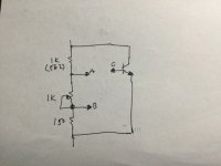

Your sketch finally helped me understand what you meant! I will confirm that the brown wire (base of bias transistor) does connect at point A. It should. Also your suspicion of what caused the catastrophic failure is probably correct. I could not get a stable or symmetrical reading off the original pots, and I think one was open, I bet they caused the chaos. Notice the bias resistors smoked off, possibly while the pot was belly up resting. Every chance I've had, those Bourns pots go in.The reflections on that back side picture make it hard to trace - you’ll have better luck with the PCB in your hand. The results you describe are as if C (brown wire) was connected at point B. The schematic shows it connected at point A. Point A is technically correct - as it easily allows the bias to be adjusted WAY down, and if the pot goes to maximum resistance this is what happens. With it connected at point B the adjustment is tricky - and if the wiper opened up on the original pot, it may have even been what caused the original failure. This wouldn’t be the first time a design error was overlooked, as it could be made to work.
If you just leave it, it will probably be “ok”, as that Bourns pot is about as good and reliable of one as you will get. I would be inclined to do one of two things. Either move the connection to where it is supposed to be, or change the pot out with a 100 ohm to limit how high the R can go in the event of pot failure/wear out. The bias probably wont go stupid high if the pot goes to 100 ohms instead of the “proper” setting of 65 with that choice of Vbe multiplier transistor. With it up at the full 1k, the bias is way excessive.
Attachments
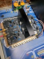
With driver board in hand, I confirmed that the brown wire (base of bias transistor) does connect at point A.
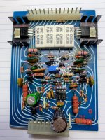
Finished the unit today, dialed bias in quite easy and assembled everything back up. Works without a glitch and produces great sound. I will take some final photos and wrap this experience up. Thank you wg_ski, and others, for your great and valuable help! Could not have achieved this great result without you. I hope this thread will help the next HP-2000 owner, it is probably the only one with this level of technical information.
To summarize, the only mod made to the entire circuit was to replace R617 with a 562 ohm resistor. The stock resistor there is 1K. This enabled the bias to be dialed down to spec (1.8 mV DC).
Attachments
Last edited:
I should have taken my own advice on the title of this thread.
The unit played well for the night, but in the morning it blew a rail fuse. Later, the other channel started showing bad behavior. After three blown rail fuses, a driver, and damaged side of outputs, I decide to cut my losses.
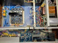
Wanting to put a lid on this project, the Wondom class D power amp that I had for another unit with NLA parts got put in. It produces 5 more watts (125) than the discrete power amp, and I can cut my lawn without the fear of coming in and finding the house smoked up. The sound is perfect, no hum buzz or anything like that. It is wired in circuit, so protection is still in, power meters and headphones work, and speaker relay as well.
So even with all new semis, electrolytic caps, many resistors, trim pots, good bias readings, and your input, this thing decided to go belly up. Like somebody said earlier in the thread, these units were fraught with problems.
Thanks for everyone's help, and may the next HP-2000 owner save money and time.
The unit played well for the night, but in the morning it blew a rail fuse. Later, the other channel started showing bad behavior. After three blown rail fuses, a driver, and damaged side of outputs, I decide to cut my losses.
Wanting to put a lid on this project, the Wondom class D power amp that I had for another unit with NLA parts got put in. It produces 5 more watts (125) than the discrete power amp, and I can cut my lawn without the fear of coming in and finding the house smoked up. The sound is perfect, no hum buzz or anything like that. It is wired in circuit, so protection is still in, power meters and headphones work, and speaker relay as well.
So even with all new semis, electrolytic caps, many resistors, trim pots, good bias readings, and your input, this thing decided to go belly up. Like somebody said earlier in the thread, these units were fraught with problems.
Thanks for everyone's help, and may the next HP-2000 owner save money and time.
Attachments
Should have listened!From my recollection of the Sherwood models, which may be like your experience of finding them to be total wrecks, there were lots of problems due to quality issues including the component types and ratings of semis so I think that if you like the sound with the Wondom modules inside, continue with those or similar which you may find already discussed in the class D forum here. It's also far cheaper and simpler than trying to restore an old, midfi product to something like its original state and to what purpose?
....
I've got an HP-1000 that uses the same driver boards. I picked up mine with one channel not working and upon inspection found one of the driver boards missing. Have you one now available?I should have taken my own advice on the title of this thread.
The unit played well for the night, but in the morning it blew a rail fuse. Later, the other channel started showing bad behavior. After three blown rail fuses, a driver, and damaged side of outputs, I decide to cut my losses.
Wanting to put a lid on this project, the Wondom class D power amp that I had for another unit with NLA parts got put in. It produces 5 more watts (125) than the discrete power amp, and I can cut my lawn without the fear of coming in and finding the house smoked up. The sound is perfect, no hum buzz or anything like that. It is wired in circuit, so protection is still in, power meters and headphones work, and speaker relay as well.
So even with all new semis, electrolytic caps, many resistors, trim pots, good bias readings, and your input, this thing decided to go belly up. Like somebody said earlier in the thread, these units were fraught with problems.
Thanks for everyone's help, and may the next HP-2000 owner save money and time.
I had the same luck until the owner found the driver board in a forgotten box and sent it. Sorry, I sold the whole thing to the next victim.I've got an HP-1000 that uses the same driver boards. I picked up mine with one channel not working and upon inspection found one of the driver boards missing. Have you one now available?
So I stumbled across this thread, new to this site. Was researching the Sherwood HP 2000 I recently got. What a trip you went on there! So far, the one I got is very interesting. Mentally trying to compare to my Pioneer SX-1010 which seems to be slightly older vintage than this HP 2000.
I'm not in love with the Sherwood's volume control -- it jumps in steps rather than the typical glide. No way of knowing what output I'm getting as I would guess these meters need recalibration. I may show it to a shop in central IN where I'm located. It hasn't behaved badly in any way at any time yet (fingers crossed). I need to A-B, this doesn't sound remarkably different than the SX-1010 so far.
I'm not in love with the Sherwood's volume control -- it jumps in steps rather than the typical glide. No way of knowing what output I'm getting as I would guess these meters need recalibration. I may show it to a shop in central IN where I'm located. It hasn't behaved badly in any way at any time yet (fingers crossed). I need to A-B, this doesn't sound remarkably different than the SX-1010 so far.
- Home
- Amplifiers
- Solid State
- Sherwood HP-2000, Resurrection, should I even bother...