Hello everyone,
I need help 🙂
I have a busted Sharp XV-C20E projector and i would like to retrofit a new lamp + ballast combo from YWH.
The current ballast is worthless, since it already blew up two JYS bulbs, so i want to take it out all together. The problem i have is as follows.
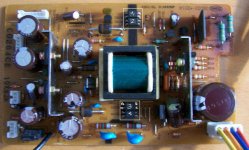
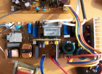
The power supply in C20E is made up of two boards. The first board is the ballast, the second board is fed from the ballast and supplies various DC voltage lines to the rest of the projector circuitry.
The second board (which i call the DC power supply), has a 4-pin connector from the ballast, with voltages as follows:
RED = 6.31
BLUE = 0.004 - 0.013
ORANGE = -0.000 - 0.006
YELLOW = 0.083 - 0.091
The BLUE, ORANGE and YELLOW lines do not have stable voltage, they float.
When i disconnect the DC power supply board from the ballast and supply 6.3V from an external power source, the DC power supply does not respond. It only powers up, when connected to the ballast with the 4-pin connector.
The ballast must send some kind of signal to tell the DC supply to fire up.
Does anyone have any clue as to what i need to do to have the DC power supply operate independently from the ballast circuitry?
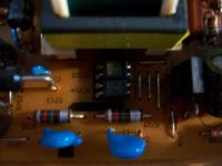
I believe i have to do something with the 4 optocouplers i've highlighted in the attached DCPS1.jpg
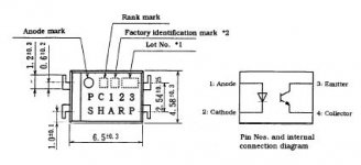
The optocouplers are Sharp PC123, datasheet attached in the next post.
I measured the voltages on the OC's, and this is what i got:
A=Anode
C=Cathode
E=Emitter
Cl=Collector
OPTO-1:
A=2.28
C=1.90
E=0.008 - 0.025
Cl=(-)0.000 - 0.008
OPTO-2:
A=4.77
C=4.46
E=(-)0.000 - 0.006
Cl=0.015 - 0.025
OPTO-3:
A=0.001
C=0.086 - 0.099
E=(-)0.010
Cl=0.072
OPTO-4:
A=0.001
C=0.083 - 0.108
E=(-)0.000 - 0.006
Cl=0.321
Any suggestions would be greatly appreciated!
I need help 🙂
I have a busted Sharp XV-C20E projector and i would like to retrofit a new lamp + ballast combo from YWH.
The current ballast is worthless, since it already blew up two JYS bulbs, so i want to take it out all together. The problem i have is as follows.
The power supply in C20E is made up of two boards. The first board is the ballast, the second board is fed from the ballast and supplies various DC voltage lines to the rest of the projector circuitry.
The second board (which i call the DC power supply), has a 4-pin connector from the ballast, with voltages as follows:
RED = 6.31
BLUE = 0.004 - 0.013
ORANGE = -0.000 - 0.006
YELLOW = 0.083 - 0.091
The BLUE, ORANGE and YELLOW lines do not have stable voltage, they float.
When i disconnect the DC power supply board from the ballast and supply 6.3V from an external power source, the DC power supply does not respond. It only powers up, when connected to the ballast with the 4-pin connector.
The ballast must send some kind of signal to tell the DC supply to fire up.
Does anyone have any clue as to what i need to do to have the DC power supply operate independently from the ballast circuitry?
I believe i have to do something with the 4 optocouplers i've highlighted in the attached DCPS1.jpg
The optocouplers are Sharp PC123, datasheet attached in the next post.
I measured the voltages on the OC's, and this is what i got:
A=Anode
C=Cathode
E=Emitter
Cl=Collector
OPTO-1:
A=2.28
C=1.90
E=0.008 - 0.025
Cl=(-)0.000 - 0.008
OPTO-2:
A=4.77
C=4.46
E=(-)0.000 - 0.006
Cl=0.015 - 0.025
OPTO-3:
A=0.001
C=0.086 - 0.099
E=(-)0.010
Cl=0.072
OPTO-4:
A=0.001
C=0.083 - 0.108
E=(-)0.000 - 0.006
Cl=0.321
Any suggestions would be greatly appreciated!
Attachments
Hi, Chaink,
From what I can tell so far, I don't think you'll be able to physically remove one of the boards from the projector....
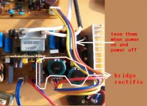
In other words, it looks like the mains input comes in on the "ballast" board (blue and brown wires next to the switch), the bridge rectifier then converts the AC mains to DC, then supplies this "high voltage DC" to the second board, which I'm certain must be the low-voltage power supply (just as you said).
So, unfortunately, I don't think you can use one board without the other.
The other thing is, I'm not entirely sure that those voltage readings are accurate - The red / blue / orange / yellow wires must surely be the high voltage DC supply from the ballast to the DC PSU board.
If you removed the ballast transformer etc., I still don't think you'll save enough room to fit a new ballast to the projector. (This is something I'm thinking about doing on an Optoma projector I just bought on eBay - the lamp is worn out, and the previous owner managed to yank the cutout switch from the PCB somehow, so it was a very easy "repair"! I still have a ballast and JYs lamp from ywh, but don't know what to use it for yet.)
Could you possibly post a photo of the underside of the ballast board around the area where the four-pin connector and bridge recitifier is? From this, we should be able to confirm what the four wires are for.
OzOnE.
From what I can tell so far, I don't think you'll be able to physically remove one of the boards from the projector....
In other words, it looks like the mains input comes in on the "ballast" board (blue and brown wires next to the switch), the bridge rectifier then converts the AC mains to DC, then supplies this "high voltage DC" to the second board, which I'm certain must be the low-voltage power supply (just as you said).
So, unfortunately, I don't think you can use one board without the other.
The other thing is, I'm not entirely sure that those voltage readings are accurate - The red / blue / orange / yellow wires must surely be the high voltage DC supply from the ballast to the DC PSU board.
If you removed the ballast transformer etc., I still don't think you'll save enough room to fit a new ballast to the projector. (This is something I'm thinking about doing on an Optoma projector I just bought on eBay - the lamp is worn out, and the previous owner managed to yank the cutout switch from the PCB somehow, so it was a very easy "repair"! I still have a ballast and JYs lamp from ywh, but don't know what to use it for yet.)
Could you possibly post a photo of the underside of the ballast board around the area where the four-pin connector and bridge recitifier is? From this, we should be able to confirm what the four wires are for.
OzOnE.
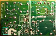
Underneath the ballast 1/2
Hey OzOnE,
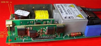
Here is the pic 1/2 of the underside of the ballast board.
Cyan box highlighting the AC input from the mains.
The DC powersupply takes 6.3V from the ballast board, but it obviously also gets a signal from the ballast on the other lines whether to switch on or not... This is what i need to bypass...
Chainik.
Hey OzOnE,
Here is the pic 1/2 of the underside of the ballast board.
Cyan box highlighting the AC input from the mains.
The DC powersupply takes 6.3V from the ballast board, but it obviously also gets a signal from the ballast on the other lines whether to switch on or not... This is what i need to bypass...
Chainik.
Attachments

Hi, Chaink,
Ok, at first I was thinking it would be a simple case of bypassing the "relay" that switches the rectified "DC mains" to the low voltage DC board, but when I looked at the top of the board again, I noticed that the relay is missing and is bypassed anyway?
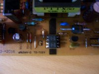
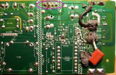
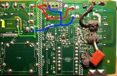
Chaink, can you confirm that there is a wire link on the top of the board above where I've marked the YELLOW part on the left-hand side of the attached photo?
If so, this would mean that the AC mains is permanently supplied to the bridge recitifier, and the rectified DC is permanently supplied to the DC board via the RED and BLUE wires (I've also marked where the "DC mains" connects to the big caps.
The GREEN line marks where the DC board would have originally triggered the relay, but this whole thing is confusing, because it's a catch-22 situation.... ie. without being supplied by the "DC mains" in the first place, how would the DC board trigger the relay?
If there are no other wires which connect between the ballast board and the DC board, I can only guess that this projector is designed so that the ballast starts first, then only powers up the DC board after the lamp has ignited???
The GREEN trace I've marked on the photo doesn't appear to be needed at all if the relay has been pre-bypassed anyway (yellow wire on the 4-pin connector). The orange wire on the 4-pin connector looks like the only wire which actually might do something to start the DC board?
I would suggest measuring the voltage between the blue wire and the orange wire when the projector is all plugged in, but be very careful, as the voltages on this board are lethal !!!! If you're using 240V mains, there should be around 340V DC between the blue and red wires on the 4 pin connector as soon as the mains switch on the projector is turned on. This is what actually "supplies" the DC board, but the question remains - does the ballast turn the DC board on, or vice-versa?
If you could also post photos of the underside of the DC board, that might give me more clues.
OzOnE.
P.S. As you might have guessed - the two blue wires (marked "2 PC 1") look like they go to the PFC (Power Factor Correction) transformer, and the two red / blue wires (marked "2 BA 1") go to the thermal cutout switch. It's possible that you could bypass both of these to save more space??
Ok, at first I was thinking it would be a simple case of bypassing the "relay" that switches the rectified "DC mains" to the low voltage DC board, but when I looked at the top of the board again, I noticed that the relay is missing and is bypassed anyway?
Chaink, can you confirm that there is a wire link on the top of the board above where I've marked the YELLOW part on the left-hand side of the attached photo?
If so, this would mean that the AC mains is permanently supplied to the bridge recitifier, and the rectified DC is permanently supplied to the DC board via the RED and BLUE wires (I've also marked where the "DC mains" connects to the big caps.
The GREEN line marks where the DC board would have originally triggered the relay, but this whole thing is confusing, because it's a catch-22 situation.... ie. without being supplied by the "DC mains" in the first place, how would the DC board trigger the relay?
If there are no other wires which connect between the ballast board and the DC board, I can only guess that this projector is designed so that the ballast starts first, then only powers up the DC board after the lamp has ignited???
The GREEN trace I've marked on the photo doesn't appear to be needed at all if the relay has been pre-bypassed anyway (yellow wire on the 4-pin connector). The orange wire on the 4-pin connector looks like the only wire which actually might do something to start the DC board?
I would suggest measuring the voltage between the blue wire and the orange wire when the projector is all plugged in, but be very careful, as the voltages on this board are lethal !!!! If you're using 240V mains, there should be around 340V DC between the blue and red wires on the 4 pin connector as soon as the mains switch on the projector is turned on. This is what actually "supplies" the DC board, but the question remains - does the ballast turn the DC board on, or vice-versa?
If you could also post photos of the underside of the DC board, that might give me more clues.
OzOnE.
P.S. As you might have guessed - the two blue wires (marked "2 PC 1") look like they go to the PFC (Power Factor Correction) transformer, and the two red / blue wires (marked "2 BA 1") go to the thermal cutout switch. It's possible that you could bypass both of these to save more space??
Attachments
Hi,
I only just noticed the small 2-pin connector on the ballast board - Is this connector usually joined to another board via a cable? If so, then this would explain where the extra signal is which starts the ballast board.
This probably means that one or more "standby" voltages are present on the DC board before the ballast is ignited; the standby circuit on another board then starts the ballast, and once the lamp is ignited, a "lamp on" signal starts the rest of the low voltages on the DC board.
The only questions are what the voltage of the "lamp on" signal is, and which connector it's on?
The "lamp on" signal is probably on the 4-pin connector (possibly between the BLUE and ORANGE wires), but it might be on another connector. What I can say for sure is that the RED and BLUE wires definitely supply the rectified "high voltage DC" to the DC board (around 340V DC !!! - be careful !!!).
The power supply might turn out to be a bit more complex than it first looks. ie. there's a chance that the small board on the ballast might generate the regulation pulses for both the ballast itself, and the DC board?? (doubful though).
Chaink - If the 2-pin connector on the ballast joins to another board, could you possibly attach a photo of the board it joins to? (plus an underside photo?).
OzOnE.
Hey Ozone, merry xmas.
Before i answer your questions, let me update you on what i've done so far.
I've verified that by simply grounding the blue and orange wires, i was able to fire up the DC power supply. The yellow wire has to do with lamp detection circuitry, which is no longer in use (RE: small two-pin connector).
To test this, i've desoldered and connected the bridge rectifier directly to the DC power supply board, bypassing the reset of the ballast circuitry. I was still supplying the bridge rectifier from the mains input part of the ballast circuitry.
I then soldered the bridge rectifier back to the ballast board and at the same time desoldered the ignitor coil, which is no longer required. I also removed the vertical lamp detection circuit board (with the small two-pin connector), as this is no longer required also. This board was connected to another part of a projector with a two-wire cable and simply removing this cable, bypasses the lamp detection routines this particular projector uses. Nice and simple. If this cable was attached to the small two-pin connector, when you try to power up the projector with the lamp missing, it won't switch on.
After i put the projector back together, i've tested the video output by placing an LED bike torch inside the lamp chamber and connecting it to a video source. When i tried this with the ignitor coil still attached, i was getting a lot of "white noise" interference - the picture would constantly has white lines flicker through it. With the ignitor coil now gone, the picture is clear and stable.
I now basically have a projector that is ready to have a new ballast + lamp wired into it.
Now to answer your questions:
(1) RE: your yellow mark - there is no link on the top of the board; i believe you are right, DC is constantly supplied to the DC power supply, as long as BLUE + ORANGE are grounded.
(2) Yes, it would seem that this projector would fire up the DC power supply only once it ignited the lamp, however if we disconnect that cable that connects the vertical riser card on the ballast to another part of the projector, the DC power supply fires up straight away without the lamp.
(3) RE: thermal cut-out/PFC transformer;
Sinc ei am stuck with the stripped ballast board anyway, i am going ot leave these two modules inside. The new ballast would have to be wires similar to the way YWH proposed in his previous reply. Although i will need to work out alternative placement since otherwise the new ballast would block the fan air intake.
Now I have some questions in relalation to the 340VDC and retrofiting a new ballast + lamp from YWH
(1) I can't seem to find 340VDC, i measured the DC output of the bridge rectifier and it measures 140V. I can't seem to find 240VAC either, the AC input to the bridge rectifier measures around 100V. Is that normal?
(2) How would i hook up this new ballast from YWH? My guess is that i would need to connect a different? bridge rectifier to my 230VAC mains and connect its output to the new ballast 340VDC input.
I am also unsure of the small three-pin power connector on the new ballast. How would i wire my on/off switch here?
Regards,
Chainik.
Attachments
Hi, Chaink,
I forgot all about Christmas for a while there! Merry Christmas to the diyaudio crew! (Actually, it's Boxing Day here now - just).
Chaink, do you actually live in Australia, or is that the default location on the profile? I assumed you're mains input was around 240VAC, but can you place confirm this?
If you are indeed using 240V mains input, I'm puzzled as to why there would only be 100V AC across the inputs to the bridge rectifier? If you have 230V / 240V mains in your house and you're only measuring around 100V between the BLUE / BROWN mains input wires, then your voltmeter can't be too healthy? (Unless of course you're connecting one meter probe to chassis "ground" / earth?? )
)
About the yellow mark on the photo - I noticed after that your ballast DOES actually have the relay bypassed, but the wire link is in place of R1773 (just above the yellow mark) - this will mean that there will always be "DC mains" supplied to the DC board via the BLUE and RED wires.
As far as I can tell, grounding the YELLOW wire on the 4-pin connector shouldn't do anything, as it doesn't appear to be connected to anything usefull at all on the ballast board (as you no doubt gathered).
When you say you're "grouding" the wires, do you mean connecting the ORANGE wire to the BLUE wire?
Without knowing exactly how the circuit works, I would be a bit worried about how it's all connected. It wouldn't surprise me if "grounding" the orange wire does start the DC board though.
The question of whether you can connect the new ballast to the + (plus) and - (minus) outputs of the original diode bridge comes down to how much power the bridge can handle, but since the original ballast parts are mostly removed / disconnected, I would have thought the original bridge could supply the new ballast with ease. (the new Philips ballasts should be quite efficient, and that bridge looks quite beefy).
I remember posting about that new ballast before somewhere (can't find it atm), but by looking at the photo, I'm fairly certain you'll only need to connect the center pin to ONE of the outside pins to start the new ballast. (The other pin looks like the "lamp lit" signal, 'cos the opto is facing the other way.)
The best thing would be to find the datasheets for the optos on the new ballast, then figure out which method you want to use to switch the ballast on - eg. short the opposite side of the "lamp on" opto with a switch, or supply the connector side of the "lamp on" opto from the projector's original "lamp on" signal??
Before doing anything else though, I would suggest confirming that you actually have roughly 240V AC between the BLUE and BROWN mains input wires (again - carefully!), then test for approx 340V DC between the + (plus) and - (minus) pins of the bridge.
You should then be able to simply solder wires between the old ballast board bridge and the new ballast board power input (making absolutely sure that the polarity is correct !!!)
I'll have a quick look for that post about the new ballast and get back to you if I find the info.
OzOnE.
I forgot all about Christmas for a while there! Merry Christmas to the diyaudio crew! (Actually, it's Boxing Day here now - just).
Chaink, do you actually live in Australia, or is that the default location on the profile? I assumed you're mains input was around 240VAC, but can you place confirm this?
If you are indeed using 240V mains input, I'm puzzled as to why there would only be 100V AC across the inputs to the bridge rectifier? If you have 230V / 240V mains in your house and you're only measuring around 100V between the BLUE / BROWN mains input wires, then your voltmeter can't be too healthy? (Unless of course you're connecting one meter probe to chassis "ground" / earth??
)About the yellow mark on the photo - I noticed after that your ballast DOES actually have the relay bypassed, but the wire link is in place of R1773 (just above the yellow mark) - this will mean that there will always be "DC mains" supplied to the DC board via the BLUE and RED wires.
As far as I can tell, grounding the YELLOW wire on the 4-pin connector shouldn't do anything, as it doesn't appear to be connected to anything usefull at all on the ballast board (as you no doubt gathered).
When you say you're "grouding" the wires, do you mean connecting the ORANGE wire to the BLUE wire?
Without knowing exactly how the circuit works, I would be a bit worried about how it's all connected. It wouldn't surprise me if "grounding" the orange wire does start the DC board though.
The question of whether you can connect the new ballast to the + (plus) and - (minus) outputs of the original diode bridge comes down to how much power the bridge can handle, but since the original ballast parts are mostly removed / disconnected, I would have thought the original bridge could supply the new ballast with ease. (the new Philips ballasts should be quite efficient, and that bridge looks quite beefy).
I remember posting about that new ballast before somewhere (can't find it atm), but by looking at the photo, I'm fairly certain you'll only need to connect the center pin to ONE of the outside pins to start the new ballast. (The other pin looks like the "lamp lit" signal, 'cos the opto is facing the other way.)
The best thing would be to find the datasheets for the optos on the new ballast, then figure out which method you want to use to switch the ballast on - eg. short the opposite side of the "lamp on" opto with a switch, or supply the connector side of the "lamp on" opto from the projector's original "lamp on" signal??
Before doing anything else though, I would suggest confirming that you actually have roughly 240V AC between the BLUE and BROWN mains input wires (again - carefully!), then test for approx 340V DC between the + (plus) and - (minus) pins of the bridge.
You should then be able to simply solder wires between the old ballast board bridge and the new ballast board power input (making absolutely sure that the polarity is correct !!!)
I'll have a quick look for that post about the new ballast and get back to you if I find the info.
OzOnE.
Erm, well, the ballast on that old post is quite similar to the new one you are using, but our original aim was to bypass the projector itself ("lamp lit" signal), and not to start a new ballast, but still, some of it applies....
http://www.diyaudio.com/forums/showthread.php?postid=950656#post950656
Basically, you just need to find the datasheets for the new ballast optos, find the opto which has it's emitter / collector pins facing AWAY from connector, then short those two opto pins with a solder blob or wire.
The new ballast should then ignite the lamp as soon as the mains switch on the PJ is turned on?
To find out which polarity to connect the 340V DC power between the old and new ballast boards, you can simply trace which of the pins connects to each pin on the large caps. (ie. "plus to plus" and "minus to minus" - old and new).
Obviously, the polarity of the DC connection between the old bridge rectifier and the new ballast MUST be correct, or there will be a seriously unwanted indoor-fireworks display when you turn on the power!!
Hope this helps,
OzOnE.
Hey Ozone,
Yes, in Australia, so its supposed to be 240VAC. I think you are right - my multimeter is hosed as it measures 100VAC at the powerpoint! I've been putting off getting a new one, but i guess its finally time to spend some money...
I am going to order the new ballast + lamp combo from YWH and hook it up using your instructions, sound spretty straight forward. The physical mounting of the new ballast would probably be the challenging bit, as there is no room inside the chassis. It would have to go on the outside inside some electronic kit box.
when i was experimenting i was connecting the orange and blue wires directly to the DC(-) pin of the rectifier bridge.
I believe the yellow wire has to do with lamp detection circuitry. When i have the riser card plugged in, this wire seems to be connected to ground (measures -0.00 ?). When i have the riser card removed, it measures about 1.6V. Since i removed all the lamp detection stuff, that part is redundant.
Thanks heaps for you help so far,
Chainik.
Hi, Chaink,
You could probably get a quite decent multimeter from "THE well known auction site 😉 " - The one I'm using now can test for capacitance and frequencies up to 20KHz, and it only cost around £16 (AUD40 ?).
The problem with measuring voltages with respect to "ground" is that the voltage levels on the power supply might be with respect to DC- (rectified mains) instead of chassis ground (which is often floating anyway.)
Also, it's not always recommended to test PSU optos with a multimeter when the power supply is working because the multimeter itself might affect the working of the power supply, and possibly cause something to blow.
OK, it looks like I was wrong about the yellow wire - I originally thought it went to the relay (which is bypassed anyway), but it does indeed go somewhere else. It's difficult to tell from the photo, but as long as your DC board is happy with the orange and yellow wires tied to the blue wire, it's probably fine.
It looks like the yellow wire does actually go to pin 2 of the riser card. I still have no idea exactly what the wires do, but as long as the bypass works, I wouldn't worry about it. Fitting the new ballast should be fairly simple.
You're lucky you have places like "Mr" Dick Smith out there to help you with project boxes etc. 😀 Shops like that are difficult to come by in the UK now. Well, we do have Maplin and shops like that, but our nearest is about 40 miles away.
Have a good new year guys.
Keep us updated with the project, Chaink!
OzOnE.
Hey Ozone,
Yep, this multimeter i was using is basically "f*cked". It also now shows the ambient temperature as 128C. I retrofited a "mains" DC adapter to bypass the battery on it a while ago, so maybe it got fried it over time - no matter it was about $30.
I am going to get this one to replace it:
http://cgi.ebay.com.au/ws/eBayISAPI.dll?ViewItem&item=190059294864
Seems like a nice DMM, true RMS and has RS232. Any comments?
You guys should have access to farnell int he UK? I think they are worldwide and have pretty much all electronic parts. Or you can just order stuff from Oz with your "pounds" - it will probably still be cheaper than buying locally 🙂
When YWH sorts his finances out, i am getting a ballast + lamp. May not be for a fdew months, but keep watching this thread, i'll post results.
Take care,
Chainik.
P.S. The only undesired byproduct of removing all the lamp detect circuitry is that now the "soft" power switch (not the mechanical one) does not turn the projector off. It only switches it on. Doesn't matter i suppose, since i will be using the mechanical switch from now on anyway.
Hi,
That DVM looks nice, but it depends on if you want to pay the extra for RS232 and frequencies up to 60MHz when a $40 one does everything else.
It's a good price for the amount of time you'll be using it I suppose, especially if it's got good software with it.
Guess how I killed my last DVM !! Yes, I tried it on a projector ballast (ignoring all the warnings), and the lamp re-ignited and arced across inside the DVM and fried the PCB tracks.
I use Farnell quite a lot in the UK, but with the minimum order amount on credit card orders (£20 I think), it takes me a while to work out what I need to buy at the same time, so I often don't end up buying anything for months!
OzOnE.
That DVM looks nice, but it depends on if you want to pay the extra for RS232 and frequencies up to 60MHz when a $40 one does everything else.
It's a good price for the amount of time you'll be using it I suppose, especially if it's got good software with it.
Guess how I killed my last DVM !!
Yes, I tried it on a projector ballast (ignoring all the warnings), and the lamp re-ignited and arced across inside the DVM and fried the PCB tracks.I use Farnell quite a lot in the UK, but with the minimum order amount on credit card orders (£20 I think), it takes me a while to work out what I need to buy at the same time, so I often don't end up buying anything for months!
OzOnE.
- Status
- Not open for further replies.
- Home
- General Interest
- Everything Else
- The Moving Image
- DIY Projectors
- Sharp XV-C20E new ballast retrofit