Going to go all in and build a PSE GM70 amp. I just want to use one ammeter and switch back and forth between the two GM70's.
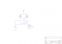
Attached is the proposed wiring and a pdf of the switch I plan to use.
Switch will be ON-ON
Is this going to be alright? Does anyone have a better way of doing this?
Attached is the proposed wiring and a pdf of the switch I plan to use.
Switch will be ON-ON
Is this going to be alright? Does anyone have a better way of doing this?
Attachments
Unless this is a Guaranteed Make Before Break switch, it will sound awful when you switch.
How much current is in each triode?
How much voltage is across the meter resistance (I can't read the value, it looks like 0.66 Ohm).
i.e. 100mA * 0.66 Ohm = 0.066V.
Put a diode directly from each cathode to ground.
Then the cathodes have a path to ground during the time the switch connections might be open. At least the change in cathode voltage will only be 1 diode drops (~ 0.6V), causing a small change in cathode current during switching (open connection) times.
And the diode will be completely off during the time the meter is in that cathode path.
Otherwise the one cathode current will drop to zero during switching times (Think what that will do as the current in the Output transformer drops to 1/2.
Ya was was thinking I need a make before break switch.
The value is 0.66 ohm and the plan is 90 mA per tube.
Diodes! Thanks!
The value is 0.66 ohm and the plan is 90 mA per tube.
Diodes! Thanks!
Fixed bias or cathode bias?
Either way a separate cathode resistor for each GM70 is the way to go. Only need a SPST switch then. Maybe an ON-OFF-ON type.
Cheers
Matt.
Either way a separate cathode resistor for each GM70 is the way to go. Only need a SPST switch then. Maybe an ON-OFF-ON type.
Cheers
Matt.
Sorry, didn't realise you would be using the meter to measure the whole cathode current.
Can you not use a 50 or 100uA meter and a shunt resistor in each cathode?
Cheers
Matt
Can you not use a 50 or 100uA meter and a shunt resistor in each cathode?
Cheers
Matt


I would definitely recommend a shunt resistor and basic meter instead of a true milli-ammeter. The risk of an open circuit at the switch while switching with HT applied to the top of the valve could be nasty, since the current could fall to zero instantaneously (not good for the output transformer) and the cathode would jump to a relatively high voltage. And even if HT was not present, the switch is a potential weak link that is best avoided.
I would definitely recommend a shunt resistor and basic meter instead of a true milli-ammeter. The risk of an open circuit at the switch while switching with HT applied to the top of the valve could be nasty, since the current could fall to zero instantaneously (not good for the output transformer) and the cathode would jump to a relatively high voltage. And even if HT was not present, the switch is a potential weak link that is best avoided.
There will be a diode to ground on each cathode that will not be part of the switching. Are you anticipating a diode failure in this setup because of the switching?
Cheers!
Mel
I would hope that a 3 Amp power diode from each cathode to ground would not fail.
We had assemblers years ago that were bending the leads by hand, right at the body, instead of bending outside of a needle nose pliers clamped to the wire right at the body. After solder flow, some diodes had failed, without even being powered up (showed up on an Ohmmeter test). When the problem was discovered, the problem got fixed by proper training.
With proper care in assembly, all the 3 Amp diodes worked.
The current transient will be the operating Gm of the tube times about 0.6V.
@ Gm ~ 6mA/V * 0.6V, the transient will be about 3.6mA.
Or use a 3 Amp shotkey, and the voltage will be about 0.3V
Gm ~ 6mA/V * 0.3V, the transient will be about 1.8mA.
The one thing I do not understand is why there is a diode across the meter (even in the original schematic).
I expected that the meter internal resistance was about 0.66.
That means for normal operating current, no diode is going to turn on (100mA * 0.66 Ohm = 0.066V). 1 amp of current will turn a diode on, but I hope the tube never goes there.
And yes, therefore the second switch leg needs a 0.66 Ohm resistor, just as shown.
OK - I missed that detail. If the diode holds, then all should be OK.There will be a diode to ground on each cathode that will not be part of the switching. Are you anticipating a diode failure in this setup because of the switching?
Cheers!
Mel
Diode across the meter?
Good question. Although I don't know why it happened there is a ~0.66 ohm resistor in the 150mA simpson meters. It actually failed in one of my meters. Suddenly the mA on the meter would start dropping and then it would go back up and it took a while to figure it out but the resistor in the meter was drifting (randomly). I replaced the resistor in the meter a while back and all has been good.
Bizarre I know, so I put diodes across them. I could have shorted it somehow during construction. (Most likely)
Going to go all in and build a PSE GM70 amp. I just want to use one ammeter and switch back and forth between the two GM70's.
Attached is the proposed wiring and a pdf of the switch I plan to use.
Switch will be ON-ON
Is this going to be alright? Does anyone have a better way of doing this?
yes, use 1 ohm resistors in the cathode circuit and switch a dc voltage meter to ground and the other side switches from one to other cathode. I personally use this along with an on-off-on switch.
I'd agree^^^
It would be so much simpler to put a 1 ohm resistor to ground from each cathode, and a voltmeter switching to the top of one or the other. No insertion switching, no momentary opens. And the 1 ohm resistor will drop 1 volt per 1 amp current, meaning each millivolt directly corresponds to one milliamp current.
And it works for either fixed bias or cathode bias. If you have a 250 ohm (made up example) cathode resistor, you can still ut a 1 ohm resistor in series with it.
OK I found two 50 microamp Simpson Meters on ebay for cheap. I should be able to pull their guts and put them in my 150mA cases. They should calibrate with ~0.6 ohms in parallel. They have 1800 ohms resistance.
New Simpson meters are getting expensive!!!
New Simpson meters are getting expensive!!!
Or take the 0.66R resistor out of the rather nice meters you have and put a 0.66R 1% resistor in the cathode of each GM70. Job done.
Cheers
Matt
Cheers
Matt
Last edited:
A related question;
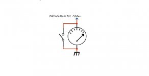
I have some nice Weston 0-100mA meters, and want to use them on the cathodes of each 300b in a fixed bias PP amp.
Plan is to place the meter between the cathode (hum balance pot) and ground, with a switched bypass around the meter. Open the bypass switch and the current flows through the meter, close the bypass and the current takes the (near) zero resistance path and flows around the meter.
Any issues?
(probably a silly question, but as an amateur, I'd rather be safe than sorry)
Attachments
Funny hey Mel, probably works out that the meters you have are 100uA full scale with 0-150mA scale markings. This would mean with the 0.66R shunt resistors there would be around a 1ish percent error at full scale, assuming the meters are linear. Not too bad at all.
So if you remove the shunt resistors from the meters you have and place a 0.66R resistor in each cathode (to preserve your 150mA scale which is ideal) you only need a SPST switch to do the duty of switching the + terminal of the meter between cathodes and the other terminal to ground. Good times.
Cheers
Matt
Last edited:
- Status
- Not open for further replies.
- Home
- Amplifiers
- Tubes / Valves
- Sharing Meter with Switch