On this link you can see a file with a ELV GmbH 200VA power inverter:
www.ecn.nl/docs/library/report/2000/c00019.pdf
Fernando Vidal
www.ecn.nl/docs/library/report/2000/c00019.pdf
Fernando Vidal
Attachments
Dear naseerak,
Sorry for being late. I was too busy and that's why was late. By tomorrow, you will get schematic and code.
You can do it by many ways but stick to micro controller and gradually you can move forward and can go for sophisticated and advanced program. Micro controller is the ultimate future in electronics. Please don't consider it at per with 555 or any other pwm ic as the capability of micro controller is far superior.
With thanks.
golam said:For pure sine wave inverter, you require 2 stage configuration- first boost section, from 12/24v dc to 350v dc and for that you require 2 pins of Pic micro controller to drive mosfets in push- pull topology. For converting 350v dc to 220/230v sine AC, you require a full bridge circuit and for that you require 4 pins if you use Unipolar SPWM routine or 2/4 pins if you use Bipolar SPWM routine.
Thanks.
FWIW: You can also skip the boost section and drive the primary with 12/24V using the transformer to step up the voltage . You use a PWM sine input to drive a full bridge. This reduces the part count and should also increase the efficiency slightly.
The advantage of going with a seperate boost circuit is if you plan to power the inverter from both a battery bank and the AC Mains. However if this is the case it would be better to boost the battery voltage to 170\340 VDC using a transformer than a buck boost circuit to maintain isolation between the batteries and the mains. If you are powering using the mains it would be a good idea to synchronize your PWM sine controller with the AC mains, Obviously it would not be wise for your PWM controller to be outputing at the Peak of the output sine wave, when the AC mains voltage is at the zero voltage crossing point. It would make sense to use a PFC controller on the AC Mains rectification circuit to accomidate brown-outs and small out of synchronization errors.
.
Very starnge
AOL
I was shocked to see your attachments in my email. as you promised to send me the schematic with pic12f675 having feedback mpwm the kind of schematic you have send me is already in my possesion but with an wxternal adc which scared me for the part count me i wonder what made you to refrtain from your promise.
Regards
Naseerak
For N-Channel
Great job!! N-Channel, Very nice design. your inverter looks very clean and i see an elegant design you know, to use a lot transformers make hard the pcb routing, and the component placement. Congratulations!
I am trying to build a 3.0kW. and i think you can help me. In the photos i see you are using an aluminum extruded case. i was thinking to use some thing like that too, but i have not found where to buy it here in Mexico.
Is it possible that you send me the contact where to get this kind of case or the manufacturer name?.
it would be so helpful to me.
What cupper thickness do you suggest to use for the PCB, and one issue that has been hard to me is the transformer calculation and suitable core selection. What is the AL for the CORE you are using.
Can you suggest me some software or tool to design transformers ?.
i would like to contact you. i am leaving you my email:
escobedo35@yahoo.es
best regards.
Hi Escobedo,
Thanks for the kind comments on the inverter. I hate to rain on your parade, but I did not build it. It is a commercial unit I was given to fix, and I was unable to find the fault. I will try to answer your questions, though.
Since I did not make the unit, I do not know where to get the extrusion, other than going to the manufacturers, like Thermalloy, Aavid, wakefield, and other heatsink manufacturers. Or, you could find a junked inverter, gut it, and use its heatsink for your unit.
For the transformers, at least when I do my own units, I use the procedure from Chryssis' book, with support from Brown's book. A little Pressman in there, too.
For the copper, I'm not sure of the thickmess, but for the low-voltage, high-current section, Copper bus bars are used. Not sure of the thickness, but I would think at least 1/16th", or 1/8th" inch thick.
Hope this helps.
Cheers,
Steve
Hi
I am working on an inverter project, sine wave inverter based on PIC micro controller. However, the problem I am anticipating is that since I would be using an Iron core transformer, would it be able to stand the high frequency, around 50-100 KHz, needed for producing sine wave. Could someone with this knowledge enlighten me if an iron core transformer could be used. I have already made a square wave inverter.
I am working on an inverter project, sine wave inverter based on PIC micro controller. However, the problem I am anticipating is that since I would be using an Iron core transformer, would it be able to stand the high frequency, around 50-100 KHz, needed for producing sine wave. Could someone with this knowledge enlighten me if an iron core transformer could be used. I have already made a square wave inverter.
comtrek said:Hi
I am working on an inverter project, sine wave inverter based on PIC micro controller. However, the problem I am anticipating is that since I would be using an Iron core transformer, would it be able to stand the high frequency, around 50-100 KHz, needed for producing sine wave. Could someone with this knowledge enlighten me if an iron core transformer could be used. I have already made a square wave inverter.
please borther dont ask for sorcecode. here is ur requerment.
http://rapidshare.com/files/163986365/scamitic.rar
I like this thread specially N-Channel post.
But i also need more information about the inverter design like N-Channel have said
can you email this to me at masterleous@gmail.com
But i also need more information about the inverter design like N-Channel have said
can you email this to me at masterleous@gmail.com
12vdc to 220 vac at 50-60 hz
Hi,
I would like to ask Mr N. Channel, refer on rods schematic at http://sound.westhost.com/project89.htm how can i convert the freq from 20khz-50khz to 50-60 hz, i would like to make normal electric house equiptment working with that supply.
I`ve tried the schematics and its success produce 220 vac but at high freq, refer on your design it will be difficult for me its pro design 😀, so i want small power maybe 300 watts at 220 vac 50-60 hz. Normal power inverter i`ve seen inside use SG3525 x2 pcs and with LM324N using trafo and convert to High Voltage DC then it will go through IRF740 x 4 pcs. It will work with most electrical house provide at least 300 W continous and 500 peak, i`m refer to tripple lite power inverter for car. its possible we can make with rods schematic http://sound.westhost.com/project89.htm ?
Regards,
Azmi.
Hi Norazmi,
The absolutely lowest frequency that the '3525 can be programmed to is 120Hz, so I don't think this would work well for you. In your Tripplite, there are actually two stages: the DC-DC boost (12V to 320V); and the DC-AC high-voltage inverter. The SG3525 runs the DC-DC converter portion just like it would for any other DC-DC converter, running anywhere from 20kHz to 50kHz. This high frequency is necessary to handle the power levels through the tiny ferrite power transformer. Ferrites do very poorly at the 120-60Hz ranges, and for this freq, you would need a BIG heavy iron-core laminate transformer, defeating the purpose of it being lightweight in the first place.
The LM324s anf the four (4) IRF740s are for the high-voltage inverter that converts the +320VDC generated by the DC-DC booster into useable 60- (or 50-) Hz by your loads. The '740s are arranged in an H-Bridge topology, with the LM324s providing the 50-60Hz driver signals forthe converter. Special circuits called boot-strap level-shifters drive the upper N-Channel IRF740s to ensure they fully turn on when driven.
Hope this helps,
Steve
N-Channel said:Hi Norazmi,
The absolutely lowest frequency that the '3525 can be programmed to is 120Hz, so I don't think this would work well for you. In your Tripplite, there are actually two stages: the DC-DC boost (12V to 320V); and the DC-AC high-voltage inverter. The SG3525 runs the DC-DC converter portion just like it would for any other DC-DC converter, running anywhere from 20kHz to 50kHz. This high frequency is necessary to handle the power levels through the tiny ferrite power transformer. Ferrites do very poorly at the 120-60Hz ranges, and for this freq, you would need a BIG heavy iron-core laminate transformer, defeating the purpose of it being lightweight in the first place.
The LM324s anf the four (4) IRF740s are for the high-voltage inverter that converts the +320VDC generated by the DC-DC booster into useable 60- (or 50-) Hz by your loads. The '740s are arranged in an H-Bridge topology, with the LM324s providing the 50-60Hz driver signals forthe converter. Special circuits called boot-strap level-shifters drive the upper N-Channel IRF740s to ensure they fully turn on when driven.
Hope this helps,
Steve
Hi,
Thanks for the great answer, fully understand now, so it will be bad idea to operate SG3525 directly at low freq, and its need LM324 to drive it through IRF740, now i understand how it work.
Mr N. Channel do you have any suggestion how LM324 drive IRF740 mosfet to get low freq? Do you have any topology that how it work with it? I would be happy to make it test to see how it works.
Regards,
Azmi.
Luka-
I may have made a mistake, I think it is 100Hz. Sorry.
Azmi-
See the two attached schematice on a 2.5kW Inverter. First one is DC-DC boost converter driven by TL494. This can be easily changed to an SG3525, and it might be easier because of the '3525's outputs being totem-pole. The second schematic is of the DC-AC Inverter, driven by a second TL494, programmed to run at 120Hz (2 x 60Hz).
This should clear a few things up.
Attachments
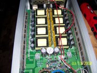
...and here is a pic of the inside. Note the eight (8) smaller xfmrs, whose secondaries are connected in series (thus guaranteeing equal current-sharing) on the high-voltage side. Granted, this is arranged to put out +160VDC (for 120VAC, RMS), but you would change the turns ratios to get the +320VDC needed to produce 240VAC RMS.....
Attachments

Hi N. Channel,
Also to LUKA, hi there your offline smps still running with good condition 😀
Phew.... whats a monster power supply lol .
.
Ah i see on your schematic, now its easy to understand and i`ve got the point. Sorry i would like to ask few question,
Vcc is 12V from batt right? Ive seen on output schematic there is lots of irf1404 mosfet so can i just make it 4 of them, ie. irfz44N? because i just need 300 watts only.... and at output mosfet is IRFP250N i would change to IRF740 4 pcs is ok with it? because i would have 240 vac at output. About the ics tl494 is ok for me i`ve it on my hand, but as you mention it can be change to SG3525AN without any adjustment? i mean for the pin leg.
And what the function for VR1 and VR2 ? freq control?
Thanks N. Channel for the schematics i`ll study and try to make pcb for it, i think it would take long time for me to design it, but i`ll try to make it work. If you willing to give me sample of the control pcb it would save my time to make it work and running.
Best Regards,
Azmi.
Also to LUKA, hi there your offline smps still running with good condition 😀
Phew.... whats a monster power supply lol
.Ah i see on your schematic, now its easy to understand and i`ve got the point. Sorry i would like to ask few question,
Vcc is 12V from batt right? Ive seen on output schematic there is lots of irf1404 mosfet so can i just make it 4 of them, ie. irfz44N? because i just need 300 watts only.... and at output mosfet is IRFP250N i would change to IRF740 4 pcs is ok with it? because i would have 240 vac at output. About the ics tl494 is ok for me i`ve it on my hand, but as you mention it can be change to SG3525AN without any adjustment? i mean for the pin leg.
And what the function for VR1 and VR2 ? freq control?
Thanks N. Channel for the schematics i`ll study and try to make pcb for it, i think it would take long time for me to design it, but i`ll try to make it work. If you willing to give me sample of the control pcb it would save my time to make it work and running.
Best Regards,
Azmi.
N-Channel said:deleted by N-Channel
- Status
- Not open for further replies.
- Home
- Amplifiers
- Power Supplies
- SG3525 for Inverter