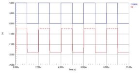
According to my simulator, 6.8k was the right value.
I brought out my cursed 2x24v 200+VA trafo today, hooked it up and the amp failed instantly. Everything connected to that trafo blows up instantly.
And thats the least you gonna hear from me about class D. I´m terminating my class d talk with this forum here and now!
I brought out my cursed 2x24v 200+VA trafo today, hooked it up and the amp failed instantly. Everything connected to that trafo blows up instantly.
And thats the least you gonna hear from me about class D. I´m terminating my class d talk with this forum here and now!

Baldin!
Falsch! Output of comparator won't go up to 5V. LM393 has open collector output. It can only sink current at logic Low, and leave output alone at logic High!
Ledmania!
R9 is not in series with the emitter! Voltage of emitter is 0,6 V. Remains 4,4. Voltage across 4148 is 0,6V, so remains 3,8 V for the two pieces of 1k. This means 1,9 mA. Until this point you don't have any deal with R9. If transistor is in normal active domain, then Ic=Ie*alpha (alpha is a little less then 1). Now you calculate voltage on R9: 1,9 mA*6,8k, and ask if the transistor was in normal active domain or saturated. Voltage on lower side of 6,8k is -19 V (negative power supply), so voltage of higher side is -19+13=-6V. Negative collector-to-base voltage is perfect for active domain with pnp transistor, so this is the end of analysis.
now when Tekko is gone(blame his cursed transformer for that),will u gentlemen correct that schematic?
i suppose that when simulations will agree then we can have a final schematic.
Sagar
i suppose that when simulations will agree then we can have a final schematic.
Sagar
Pafi:
Hmmmm, of cource you are right ..... I was a bit too fast there only wanting to simulate the levelshifter alone ... sorry😱
As you calculation (and my updated sim) shows it is only aff by a single volt (voltage at pin 2 being -6 instead of -7 volt) which shouldn't do any harm.
Tekko:
(if you are still reading this thread) glad to hear that your simulated it all. Do some more testing and measuring. Start without the driver and output mos.
And do get yourself a bread board ... it's the only way to go, as simulations does not at all say it all, and a lot of tweaking is necessary.
Get up on the horse again😉
Baldin!
No problem! But I start to think that simulators make experienced people too lasy, and beginners toooo self-confident.
Sugarverma!
I'd rather design a new one, but I don't have so much time. And I don't know the exact requirements. (full-band or only sub, maximal supply voltage, load impedance, input voltage, etc...)
The class d amp will be put to the service of a subwoofer with 400w continous rms rating.it will be used in car and so 200w would be more than enough.SMPS can supply any voltage required(diodes are rated at 600v).
Sagar
Sagar
- Status
- Not open for further replies.
- Home
- Amplifiers
- Class D
- SFX Class D subwoofer amplifier modification

