actually i want to use that amp in my car.i have a smps in the car giving output as + - V. I will be replacing TDA729x amps in the car bec they are big(mostly bec of heatsink).
so i want the amp to be able to hook up directly to the smps without unnecessarily straining it
moreover,isnt a dual supply version better than the single supply one?
can anyone suggest the requisite changes?
so i want the amp to be able to hook up directly to the smps without unnecessarily straining it
moreover,isnt a dual supply version better than the single supply one?
can anyone suggest the requisite changes?
at least..can anyone check the schematic given at the website and tell wether its correct or not?
i want to make a class d amp,dual supply one.
this one is too simple and so attracts me.
the other one is complex but promises good quality.
i will finish this one and come to that pretty soon(provided this one is correct)
can anyone check it for errors?
this one is too simple and so attracts me.
the other one is complex but promises good quality.
i will finish this one and come to that pretty soon(provided this one is correct)
can anyone check it for errors?

hi Tekko,
thank u for your reply.🙂
BTW,is the single supply schematic correct....if i go with that only then is that safe....?
power part....hw can that be corrected(tested) in your version?
thank u for your reply.🙂
BTW,is the single supply schematic correct....if i go with that only then is that safe....?
power part....hw can that be corrected(tested) in your version?
I have simulated the pulsewith modulator, tho the triangle was more of a sine it seemed to work.
But i´d still rdcommend you to build the thunderball after the original schem from the author. If you wanna build a split supply amp, try Titanchen´s circuit.
But i´d still rdcommend you to build the thunderball after the original schem from the author. If you wanna build a split supply amp, try Titanchen´s circuit.
so single supply version schematic is ok.then i will make it bec it looks so easy!
Titanchen´s circuit<<<<<<<will give it a try when i find it.
i think that the circuit of thunderball is gerived from crown audio ckt which is single supply and uses bca topology.
Titanchen´s circuit<<<<<<<will give it a try when i find it.
i think that the circuit of thunderball is gerived from crown audio ckt which is single supply and uses bca topology.
I think there is a mistake in the original schematic, if u compare BCA. Either the audio or Triangle has to go into common inv or non-inv input of comparator, and the other signal has to go inverted into the other end.
You can easily convert this circuit into +- supply with level shifting plus you get an advantage of providing global feedback for good sound quality.
Best of luck,
ajazz
You can easily convert this circuit into +- supply with level shifting plus you get an advantage of providing global feedback for good sound quality.
Best of luck,
ajazz
Power the Quad Opamp and the comparator with a dual supply like +-5V. Level shift the output of the comparator with a pnp tansistor like MPSA92 to the neg rail of +-HV with a 560ohms on the emitter to +5 and a 1Kohms on the collector to -HV. Feed the output from the collector to IR2113 or other mos drive. Take a voltage divider feedback from the output(after coil) and feed in the non-inv input of first opamp and Wow ! ! ur amp is ready.
If u want I shall draw the schematics by today evening & shall post it. But I would prefer u try it first and let us know.
best of luck
ajazz
If u want I shall draw the schematics by today evening & shall post it. But I would prefer u try it first and let us know.
best of luck
ajazz
Hi Ajazz,
If i had known what to do i had not been here askin for help😉
plz do the schematic.
Sagar
If i had known what to do i had not been here askin for help😉
plz do the schematic.
Sagar
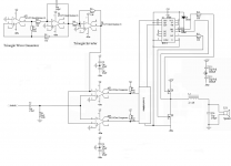
hi tekko
thanks for the schematic.
what is the Power output of this circuit?
moreover mosfets>>IRF540 or ^640(the pic reso is not good)
regarding the inductor whats the core,dimensions,wire thickness turns etc?
the circuit looks too simple to be true🙂 .
Sagar
thanks for the schematic.
what is the Power output of this circuit?
moreover mosfets>>IRF540 or ^640(the pic reso is not good)
regarding the inductor whats the core,dimensions,wire thickness turns etc?
the circuit looks too simple to be true🙂 .
Sagar
- Status
- Not open for further replies.
- Home
- Amplifiers
- Class D
- SFX Class D subwoofer amplifier modification