Again, Anton, I'm in your debt. I'll check out Newark.
I've heard varied opinions on the value of the SMT PPS chips to be used. Anywhere from 200 to 430nf. Also that the MSB pin should have a differing value from the rest.
What's your take on that?
Thanks,
Dan
I've heard varied opinions on the value of the SMT PPS chips to be used. Anywhere from 200 to 430nf. Also that the MSB pin should have a differing value from the rest.
What's your take on that?
Thanks,
Dan
Personally, I just stick near the stock values. I've found that upping the value changes the sound, but doesn't necessarily improve it. I usually go for 100nF, except for the MSB, where I go for 220nF.
Again, gentlemen, my thanks!
I'll check out Newark for those AVXs, and post back when I'm done with FrankenPhilips🙂
Oh, also, in quick study, the simplest way to do what I want is to jump out the RVC as per SoNic_real_one's instrictions; that way the muting circuit stays intact.
Am I correct in this thinking? I know that it's adding a bit more wire and other impedimenta (and the purist in me hates that) but I can't see a more straightforward way without eliminating the desirable muting circuit.
Dan
PS Just checked out Newark--they don't seem to list AVX PPS caps, only ceramic and tantalum....the search continues
Last edited:
Actually, that muting circuit is anything but desirable. The transistors the it comprises of present a significant non-linear capacitance to the signal during normal play. To remove them is a very common mod.
However, sometimes you will find that your player will have nasty habits that the muting circuit covered up before, such as noise when powering on and off. Best idea is to do the mod, see what happens and reverse it if necessary.
Best of all; replace it with a relay.
However, sometimes you will find that your player will have nasty habits that the muting circuit covered up before, such as noise when powering on and off. Best idea is to do the mod, see what happens and reverse it if necessary.
Best of all; replace it with a relay.
Hi Anton,
That's what I meant by desirable...in removing the muting circuit in the CDB-650 and CDB-471/472 a loud "pop" was produced during power cycling (easily avoided by CDP being first on/last off) but also, most annoyingly, during track changes.
It looks as though the same would apply here as that part of the circuitry seems pretty consistant.
The relay idea is intriguing, but, probably useful for only the on-off transients. Have to look into it further.
Would upgrading the quality of the transistors used be of benefit, or do you see it as an inherent flaw in the overall implementation?
Thanks Again,
Dan
I guess JFETs would be better, but I'm not sure exactly how you would tie them to what's already there.
The main player I'm listening to right now is a Rotel RCD-855 (another SAA7210 > SAA7220 > TDA1541A based player) with an aftermarket output stage of my own design. This output stage uses a muting relay is exactly the same way a stock player uses a muting transistor, that is it shorts the output to ground during powering on and off.
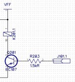
Circuit description (see pictures 1 and 2): J101.1 is connected to the KILL or MUTE signal on the mainboard (test point 93), which goes to the base of transistor Q201 through base stopper resistor R203. This causes relay K201 to become energized when the MUTE signal is high. K201 then closes and shorts the output to ground.
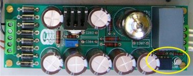
You can see the output stage in the third picture, the muting section is circled.
This circuit presents no capacitance to the signal, and is about 95% as effective as the transistors. It works well for me!
The main player I'm listening to right now is a Rotel RCD-855 (another SAA7210 > SAA7220 > TDA1541A based player) with an aftermarket output stage of my own design. This output stage uses a muting relay is exactly the same way a stock player uses a muting transistor, that is it shorts the output to ground during powering on and off.
Circuit description (see pictures 1 and 2): J101.1 is connected to the KILL or MUTE signal on the mainboard (test point 93), which goes to the base of transistor Q201 through base stopper resistor R203. This causes relay K201 to become energized when the MUTE signal is high. K201 then closes and shorts the output to ground.
You can see the output stage in the third picture, the muting section is circled.
This circuit presents no capacitance to the signal, and is about 95% as effective as the transistors. It works well for me!
Attachments

I think the capacitance of the transitors is greatly overestimated. That is a circuit with 200 ohm impedance (usually) - the CE capacitance makes no difference in 0-100kHz range. Non-linear or linear... Otherwise, those transistors won't be able to work at MHz that are specified in the catalog.
As a curiosity - does you relay "flip" between the discs change or between songs? I never measured when the "kill" signal comes on.
I guess a reed relay is fast enough for the job.
As a curiosity - does you relay "flip" between the discs change or between songs? I never measured when the "kill" signal comes on.
I guess a reed relay is fast enough for the job.
Last edited:
Very neat work-nice, efficient design!
20 years ago I'd have been tempted to try to build one for myself, but I don't have the equipment, time, eyesight 😉 (or patience) for prototyping anymore.
For now I'll just stick with either leaving it in or (temporarily) removing it.
Take Care,
Dan
20 years ago I'd have been tempted to try to build one for myself, but I don't have the equipment, time, eyesight 😉 (or patience) for prototyping anymore.
For now I'll just stick with either leaving it in or (temporarily) removing it.
Take Care,
Dan
As a curiosity - does you relay "flip" between the discs change or between songs?
No, just during power on and off. I think the player uses a soft mute in the SAA7220 during track changes.
Just checking in....
Hi Guys!
Using SoNic_real_one's recommendation, I did a bit of work to the RVC board.
I removed the 4 100uf NP caps, replacing the first pair (C2107/C2108) with a pair of low ESR Panasonic 330uf/25V caps (bypassed with .01uf Panasonic PPs) that I had in stock. I mounted them with the (-) towards the output. I then jumped to the indicated pads using 22ga 5n silver solid wire that I had on hand, insulated with teflon tubing (I didn't have any small gauge shielded wire around-I'll have to do some shopping). As I'm not in a very RFI rich environment, I've not noticed any problems.
The sonic difference was night and day--and that's an understatement.
I didn't pull the muting transistors yet-that's next. I want to let the new caps burn in first.
Thanks very much for your advice.....
Dan
Attachments
- Status
- Not open for further replies.
- Home
- Source & Line
- Digital Source
- Service Manual/Schematic Philips CD680