Hi,
I've just obtained a Philips CD680. It's in REALLY good shape, but it does need a little help sonically. I've modded many Magnavox models in the past, and the layout of this player is similar to the Maggie 471/2/3, but the mainboard is different, including a daughtercard for the analog outouts.
I've searched the 'net to the best of my ability and turned up nothing in the way of a service manual, or even much info at all on this player. It uses the venerable tda1541/saa7220 set.
If anyone here could help me, I'd very much appreciate it.
Thanks in advance,
Dan
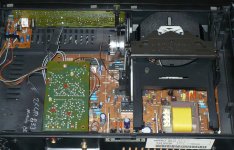
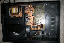
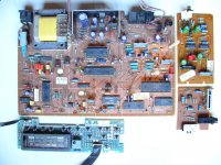
I haven't seen the manual for this player around before, but most likely it's very similar to or the same as a few other Philips players. If you take a photo of the player's internals from above, I (or someone else here) should be able to find which manual will suit you best.
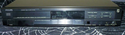

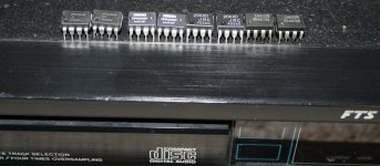
Looks like my Sylvania CD1473 (that is actually a Philips CD473). TDA 1451, LM833... Yours has the headphone output on the right side, mine on the left (under the CD tray).
Attachments
Last edited:
Thanks for the help!
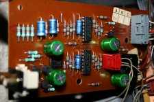
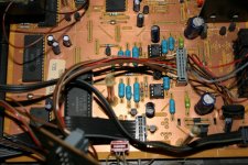
Does your CD1473 have a remote volume control? The inverted board on this one has a pair of MC14051BCPs feeding an NE5532 to the L+R line level outputs. Looks like this would be part of a remote volume control setup.
Dan
Does your CD1473 have a remote volume control? The inverted board on this one has a pair of MC14051BCPs feeding an NE5532 to the L+R line level outputs. Looks like this would be part of a remote volume control setup.
Dan
Here's a shot of the daughterboard....
My guess would be that the red connector carries the R+ L+ and ground to the board. That's another reason for wanting the schematics.
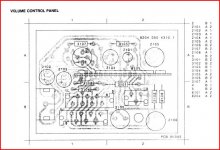
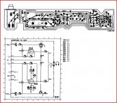
The CD473 daughterboard appears to be different from this. I've posted the image from the CD473 Service Manual as well.
My guess would be that the red connector carries the R+ L+ and ground to the board. That's another reason for wanting the schematics.
The CD473 daughterboard appears to be different from this. I've posted the image from the CD473 Service Manual as well.
Attachments
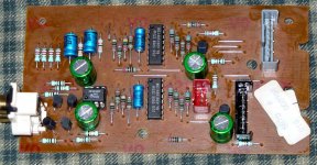
Yes, the board that is upside-down is the volume regulator with MC14051 and a NE5532 made by JRC (as a buffer). And yes, it has a remote that can control the output volume.
The one from the manual (that you posted) is the headphone regulator (has an separate buffer and an analog pot).
I have removed the LM833 from the main board and rolled some other OpAmps in that location. The best sound IMO was with LM4562.
The one from the manual (that you posted) is the headphone regulator (has an separate buffer and an analog pot).
I have removed the LM833 from the main board and rolled some other OpAmps in that location. The best sound IMO was with LM4562.
Attachments
Last edited:
Thanks!
I've had some pretty good luck with the 4562s as well, but they sound a bit "harsh" at times. I've been playing with the AD8620ARZs and those do well in my CDB650.
I'd really like to bypass all of that R/C volume circuitry and the extra op-amp, as I've no need for the R/C volume (and I don't have the remote, either).
I've also added an image of the "headphone board" from the CD473 S/M.
Maybe there are a few revisions not accounted for in the manual that I have.....
Dan
Attachments
Don't worry about the headphones board, it is not in the way.
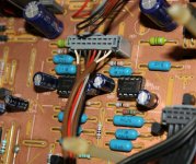
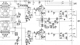
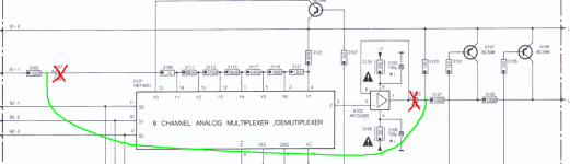
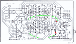
The gray connector brings the audio from the mainboard to the volume reg - you can bypass that. Just pull the big, green 100uF capacitors out and use a shielded conductor between the empty holes. Or you can leave only one capacitor in place to block the eventual DC offset component...
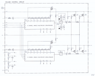
Or, if you look on the mainboard, there is a area with empty places where was supposed to be a fixed volume output. You can "build" that one.
PS; There where more that 5 "revisions" for the CD473, mine is similar with the ones labeled 01r, 05r, 07r 🙂
The gray connector brings the audio from the mainboard to the volume reg - you can bypass that. Just pull the big, green 100uF capacitors out and use a shielded conductor between the empty holes. Or you can leave only one capacitor in place to block the eventual DC offset component...
Or, if you look on the mainboard, there is a area with empty places where was supposed to be a fixed volume output. You can "build" that one.
PS; There where more that 5 "revisions" for the CD473, mine is similar with the ones labeled 01r, 05r, 07r 🙂
Attachments
Last edited:
Thanks for the info.....I'll check out the main board for those islands. That's why I'm trying to get an S/M.
I can see where you can jump out the VC on the daughterboard, but, then, where are the actual output caps? Would they then be 2107/2108?
In the CDB650/CDB472/CDB471/CDB852/CDB465/CDB460 etc. they're typically a pair of 47uf 16-25v polarized caps, and I generally replace them with a pair of 220-470uf 25-35v caps bypassed with .01uf PS or PP caps.
I'm also figuring that 6107-6110 are part of the muting circuit....
Is there any possible way that you could copy your manual, and send/email/whatever it to me? I'd be happy to compensate you for your time and trouble. I only ask because you seem to have the proper revision. The other copy that I have must be a MUCH earlier one (if not the first).
Dan
Great, those pictures did the job.
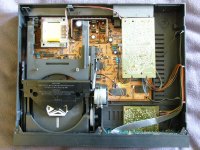
Your player shares its case (and almost certainly its display PCB) with a Marantz CD65DX. The only difference is that the CD65DX doesn't have a volume control (an advantage in my opinion), in this respect your player is the same as a Philips CD782.
Here are some pictures of my own Philips CD782:
Your player shares its case (and almost certainly its display PCB) with a Marantz CD65DX. The only difference is that the CD65DX doesn't have a volume control (an advantage in my opinion), in this respect your player is the same as a Philips CD782.
Here are some pictures of my own Philips CD782:
Attachments
Hi amc184!
I guess the only real difference is the slide pot instead of the rotary for the headphone volume. That's pretty much identical to the Magnavox CDB473 (again, later generation-not R1).
I'll search about for a Philips CD782 S/M. I wonder why Philips would have 2 CDPs with almost identical boards and 2 different Model #s...Maybe the transports are different?
Thanks!
Dan
I guess the only real difference is the slide pot instead of the rotary for the headphone volume.
Your player has the same headphone board as the CD65DX.
I'll search about for a Philips CD782 S/M. I wonder why Philips would have 2 CDPs with almost identical boards and 2 different Model #s...Maybe the transports are different?
Philips did this quite a lot, there are many cases of two or more of their players being 90% the same as each other, as well as all of the Magnavox, Loewe, Marantz etc rebrands. The Philips CD680 is very close to being a straight rebrand of that Marantz CD65DX (or rather the other way round, the Marantz would be the rebranded player).
Thanks for the info, Anton!
I've always had a fondness for the Philips/Magnavox/Sylvania/Marantz family of TDA1541 based CD players.
I would also swear that, back in the 1980's I had seen a "Philco" branded CDP-560 at a local Montgomery Ward store. I'd LOVE to get my hands on one of those just to complement the Maggy CDB-560/Sylvania CD-1560 twins that I've got in my collection.😀
Thanks again to you and SoNic_real_one for your invaluable help!
Dan
CD473
Why so many models? Pure marketing.
And yes, you have guessed, the output caps become the C2107/2108.
Or you can try to "build up" the fixed output part from mainboard, the schematics has all the parts shown. This so you won't "ruin" the value 🙂 Althou, if you don't have the remote, it is kind of worthless that control.
Last edited:
My collection is almost entirely Philips', it seems like not many of the rebrands made their way out as far as New Zealand. I've got a couple of Marantz players, and one Magnavox, but that's it.
As for modifications, here's what I would look at doing:
- Scrap the output board and reinstate the rest of the output stage on the mainboard (look at the CD65DX as the example), using better op amps and coupling caps (preferably with film caps). Remember that just because it was using a 47uF or 100uF electrolytic it doesn't mean you have to go with such a high capacitance film cap. Usually 10uF or below will work fine, just keep an eye on the rolloff frequency of the HPF you are making.
- Replace every electrolytic cap in the player. This is as much for reliability as it is for sound quality, all the elcaps will be well past their best at the age of this player. By default, just use good quality high temperature caps (such as Nippon Chemicon KMG). To decouple the DAC and output stage op amps use low impedance elcaps (such as Nippon Chemicon LXV, LXY or LXZ). The decoupling cap for the SAA7220 is particularly important, use an ultra low impedance cap here, preferably a solid electrolyte type (such as Nippon Chemicon PSA). Farnell stocks all the types of caps I have mentioned.
- Replace the SMT ceramic caps under the TDA1541. Some people use radial leaded through hole caps for this, but I prefer the SMT PPS film ones by AVX. You get the improved performance of a film cap and the neatness and mechanical stability of replacing SMT with SMT. Again, Farnell stocks these caps.
- Install an aftermarket master clock. This is often the single biggest improvement for a CD player. Make sure is is connected directly to both the SAA7220 and the SAA7210. Don't feed the clock to the SAA7210 via the SAA7220's buffer!
That's all I've got for now, I'll post some more ideas later.
SoNic_real_one: thanks very much for the link!
Anton:
Those would pretty much be my plan as well. I'm hoping that the CD-65DX board will point the way to a direct line out. I'd like the idea of variable output if I were to go direct to an amplifier, but I think that all of the extra circuitry would degrade the SQ to an unreasonable degree. HOWEVER, it might be cool to keep these outputs active and just add another pair of RCAs for the "direct out".
I don't have access to Farnell, which appears to be a great source of the type of materials that the modder would need.
I'll have to check on the availability of the AVX caps. A much neater option than what I've done previously: replacing the SMs with 1uf stacked film Panasonics. A bit cumbersome when you're doing 14 of the little suckers...
I've not ever found a reasonably priced source for the Nippon caps, so I've standardised on low ESR Panasonics. Sadly the series that I had most used back in the 80's is now discontinued, but I still have a fair supply.....
Thanks again to both of you for your help! I hope that some others can jump in and participate as well, as I'm ALWAYS willing to learn something new!
Take Care,
Dan
I don't have access to Farnell
Oh, right, for some reason when I was posting I thought you were in the UK. Farnell and Newark are one and the same, Newark would be your best source for the components I mentioned above.
- Status
- Not open for further replies.
- Home
- Source & Line
- Digital Source
- Service Manual/Schematic Philips CD680