There are multiple protection circuits that drive to pin 16.
I'm assuming that you didn't find Q85-87.
Did you try lifting Q14 to see if that made a difference?
Be careful after disabling any protection circuits.
I'm assuming that you didn't find Q85-87.
Did you try lifting Q14 to see if that made a difference?
Be careful after disabling any protection circuits.
I could not find Q85 and Q87. They don't seem present on the circuit board.
When lifting Q14 all protection problems are gone. I can attach a load from 4 ohms to the amplifier and nothing happens (also no extra current pull).
When lifting Q14 there is also no protection when higher the voltage to 14.4v.
The idle current pull at 14.4v is 2.12a
It seems to work properly then, as well as giving a nice (50Hz test tone) to the resistance bank.
Post the DC voltage on all terminals of the LM393 closest to the transformer.
Pin 1:
Pin 2:
Pin 3:
Pin 4:
Pin 5:
Pin 6:
Pin 7:
Pin 8:
Pin 1:
Pin 2:
Pin 3:
Pin 4:
Pin 5:
Pin 6:
Pin 7:
Pin 8:
So,
PS voltage of 10.9v
Pin 1: 4.77v
Pin 2; 4.98v
Pin 3; 6.39v
Pin 4; GND
Pin 5; 2.54v
Pin 6; 1.58v
Pin 7; 4.76v
Pin 8; VCC 10.9v
PS voltage of 14.28v (Q14 disconnected)
Pin 1; 5.16v
Pin 2; 4.98v
Pin 3; 8.33v
Pin 4; GND
Pin 5; 2.54v
Pin 6; 2.18v
Pin 7; 5.16v
Pin 8; VCC 14.28v
Collector Q14 (usually connected to Pin 16 TL494 is now 14.44v)
This isn't the cause of the protection.
Side note, you can copy/paste the list of pins instead of retyping them.
Is R316 near the other LM393 burned?
Side note, you can copy/paste the list of pins instead of retyping them.
Is R316 near the other LM393 burned?
Hmmm, very strange.
The resistor R316 is OK, this is a 30K resistor (I measured from my other good working amps).
The resistor R316 is OK, this is a 30K resistor (I measured from my other good working amps).
Replaced the Q14, just to be sure that transistor is not leaking.
This also wasn't the solution.
I tried to track down the paths to see which parts could be leaking some voltage to Q14 which is connected to Pin 16. Also I measured all resistors which are connected to the transistor in a short range to see if there was a bad one.
I couldn't find any.
Does anybody has an idea what could be wrong?
I don't know if I posted this before. It's a similar circuit but not identical. You'll have to compare to what you have.
http://www.bcae1.com/temp/SLA1500.pdf
http://www.bcae1.com/temp/SLA1500.pdf
I measured Q14 on my other good working power supply amplifier (it has a defect output section) and that amplifier measures the exact same voltages on the Base and Emitter. The Collector of Q14 stays at 0.004v on the good working amp (both Q14 collectors are disconnected from the board), while the Collector of Q14 of the bad protection amp goes up to the Base and Emitter voltage.
So the base and emitter voltages are identical on both amps, but it has different influences on the collectors of the transistors 2T (MMBT4403)
So the base and emitter voltages are identical on both amps, but it has different influences on the collectors of the transistors 2T (MMBT4403)
The collector's circuit is driven by other transistors or possibly comparators, In some amps, it's the Q85, 86 and 87 group (off of collector of Q87) but you said that your amp doesn't have those. It may have a similar group.
Perry,
I checked again, while searching for some issues with the SLA1500 wiring scheme. Very hidden under a bunch of wires and steel strips I found the transistor group Q85, Q86 and Q87 🙂
I checked again, while searching for some issues with the SLA1500 wiring scheme. Very hidden under a bunch of wires and steel strips I found the transistor group Q85, Q86 and Q87 🙂
Lifting the collector of Q87 does not make a difference unfortunately
Attachments
Last edited:
Do you have a D29 that connects between pins 3 and 16 of the 494? If so, remove it. Does that make a difference?
Removing D29 does not make a difference in voltage on pin 16.
The only difference it makes is that it does not go into protect (when I connect Q14 and Q87), but the amplifier is making a very bad scratchy sound.
The only difference it makes is that it does not go into protect (when I connect Q14 and Q87), but the amplifier is making a very bad scratchy sound.
Attachments

Last edited:
What happens with Q14 and Q87 out of the circuit?
Having the diode out of the circuit is preventing the protection from latching.
Having the diode out of the circuit is preventing the protection from latching.
No, the scratchy noise is gone.
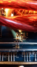
I just noticed, maybe this has something to do with it or could give a possible clue.
The 2 attached photo's are measured from the back of the power supply fets.
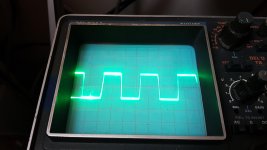
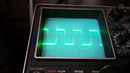
Photo with the very clean pwm wave is with a PS voltage of 10.9v
Photo with the peak in the pwm is with a PS voltage of 14.4v
This peak starts to rise around 12.8-13.0v of PS voltage when the amp is normally going into protect.
I just noticed, maybe this has something to do with it or could give a possible clue.
The 2 attached photo's are measured from the back of the power supply fets.
Photo with the very clean pwm wave is with a PS voltage of 10.9v
Photo with the peak in the pwm is with a PS voltage of 14.4v
This peak starts to rise around 12.8-13.0v of PS voltage when the amp is normally going into protect.
Attachments
Last edited:
The transients shouldn't cause a problem.
As is, will the amp produce audio at the voltages where it would go into protect?
As is, will the amp produce audio at the voltages where it would go into protect?
- Home
- General Interest
- Car Audio
- Service manual Excursion HXA5k / Soundmagus X3500