..a design like this is "ripe" for a series crossover:
Zaph|Audio
It also alleviates those concerns about single-element series filtration of tweeters.
Zaph|Audio
It also alleviates those concerns about single-element series filtration of tweeters.
..a design like this is "ripe" for a series crossover:
Zaph|Audio
It also alleviates those concerns about single-element series filtration of tweeters.
That's a neat idea, will you share your crossover when it's finished?
Even with "superfluous" parts, it will probably sound pretty nice.
😀
Best Regards,
TerryO
can anyone describe how you go about measuring the actual frequency response of the seperate speakers with series crossovers? I mean with parallel crossovers you can hook them up, and measure the frequency response. But I dont see how you can do the same with a series crossover, especially if you are adding any additional components, ie trying to get more that 6db. Or am I making it more complicating that it needs to be.....
I've used that combination of drivers quite a bit and they are more suited to an AR Series xo than the standard Series xo due to the woofer breakup at 4k-5k.
The AR Series will give steeper roll offs for both the tweeter and woofer compared to the standard series and adding a zobel to the AR Series will help to drop the breakup on the woofer lower. In addition with the AR Series xo you will get better phase over the crossover region and a nice amp friendly impedance curve.
With the quantity of drivers you have, a 2.5 way is a good option (0.5 woofer wired in parallel outside the AR Series xo).
It's been mentioned previously but Jeff Bagby's SCD is a good tool.
Series Crossover Designer
The last 2-way I built using these drivers had an AR Series xo with 15uF + 5R6 + 1.5mH + 0.15mH, zobel 4.7uF + 8R2, tweeter -ve polarity. I've included the values if you want to play in SCD.
can anyone describe how you go about measuring the actual frequency response of the seperate speakers with series crossovers?
If you have the pair of drivers, it's fairly simple. For instance, if you want to measure the woofer, disconnect the leads from the tweeter -- but install the unconnected tweeter in its place. Then, add extensions to the leads, and run them out the box a ways and hook up to the other tweeter. Put it under a box with sufficient damping/absorption material so it won't contribute to the woofer being measured. If you've got a vent, the leads can be run out of that. Otherwise, maybe out the terminal cup somehow. An external crossover is useful for this. Repeat for the tweeter.
In my newbness to passive crossovers, I've found that putting a small coil in parallel with the tweeter works better than a cap in series for a little extra tweeter protection. Sort of a shunt coil...but model it as a damped RL leg.
I stumbled across that on Troel's pages in one of his projects...which Troel's designs are the only ones that I can seem to replicate with regards to series crossovers. Tony Gee's designs are way off in the sims that I know how to do.
You guys probably already knew that stuff though. But like I said, I am a complete newb to designing passive crossovers...never had to do it before since I always had active solutions in the car, but a lack of space and money for another couple of amps and processors forced me to learn up on passives for this application.
But then again, I might be putting more work and thought into all of this considering where it is going.
The one thing that gets me is how the tweeter "legs" out on the very bottom end of it's curve (if that makes sense) in the sims. I'm not sure how this plays out to output, tweeter protection, or if it's really a concern at all. My little Scan D3004s are pretty roubust for a small tweeter, but I really can't be affording to replace these guys.
You mean you have 2 coils across the tweeter points, which both connect at the input node without a cap in series between them? That just effectively parallels the 2 coils for a lower value and reduced DCR, hence- no net gain. This probably means I misunderstand what you are referring to. If there is a cap in between, then it's a 3rd order electrical HP on the tweeter.
Please clarify...
Maybe this graphic will help you tell us what you have:
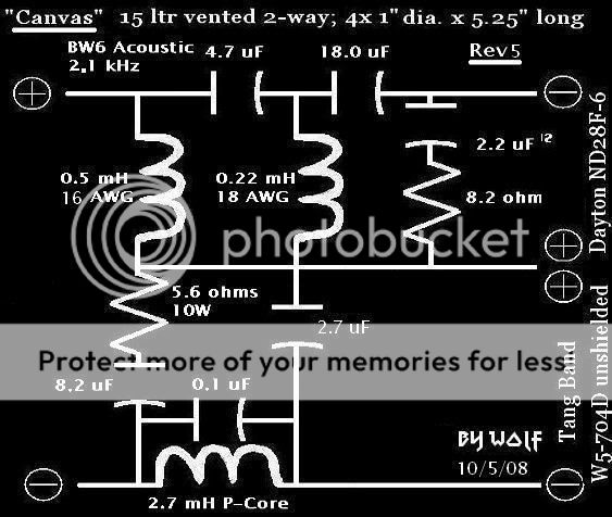
Just omit what is not there, visually through text...
Later,
Wolf
Please clarify...
Maybe this graphic will help you tell us what you have:
Just omit what is not there, visually through text...
Later,
Wolf
Well this is cool...using the "trinity" diagram/arrangement I was able to eliminate 3 parts and get the same transfer function and curve. I went from 8 parts to 5 parts in the crossover.
Also keep in mind this is for the car and I have plenty of EQ that will take care of the bumps and lumps, so I can deal with a bare bones crossover.
OKay- that's actually a padded 3rd order. The coil and parallel resistor are modeled in that position or flipped. They both yield the same result.
As to 'Trinity', you mean from Andy G? ARGOS loudspeakers
I can't find a 'trinity' on troels' website. Can you show me that?
Curious,
Wolf
As to 'Trinity', you mean from Andy G? ARGOS loudspeakers
I can't find a 'trinity' on troels' website. Can you show me that?
Curious,
Wolf
Sorry it was not the Trinity example, but the one where there are no components in series with the speakers.
Constant voltage makes the crossover sum flat. Haveing both drivers at the same impedance is necessary at the crossover frequency. This is achieved by finding the correct resistor values in the tweeter circuit. R1 and R2, assuming the correct value cap and coil are used.
Constant voltage makes the crossover sum flat.
No- constant voltage sensitivity makes the FR sum flat.
Having both drivers at the same impedance is necessary at the crossover frequency.
No it's not. You can mix impedances and still have a flat summation with constant voltage sensitivity as the drivers reproduce it via padding with only a series resistor at times.
Later,
Wolf
I wouldn't argue with the AES papers writen by Ashley,Small and Kaminsky. One of these is titled constant voltage crossovers.
All I'm saying is that there is more than one way to make flat-FR with SXO's. You brought this same stuff up over on the PETT board a while back.
You did notice I changed the terms, didn't you? Since all speakers operate on voltage, referenced to 2.83VAC, you are applying thought to a constant voltage sensitivity at the completion of the measurements and simulations. That's all there is to flat FR in a nutshell.
Now- driver blending and relationships through the xover vary greatly and can be done tons of different ways.
Later,
Wolf
I have run into to many people who think you can design a flat frequency response just by using a computer program. Be it the crossover and or enclosure. I know of people in the industry who have attempted this and they found it takes a considerable amount of time. Months of testing the crossover and cabinet design before the final design is settled on. This means testing the old fashioned way. A few examples are Bud Fried and Shane Tenace. It would also seem the definition of a t-line has changed.I wouldn't argue with the AES papers writen by Ashley,Small and Kaminsky. One of these is titled constant voltage crossovers.
Last edited:
- Status
- Not open for further replies.
- Home
- Loudspeakers
- Multi-Way
- Series crossover