Okay I see...
I was not aware of the limit in input...
All ways good to learn new stuff.
So I really need an opamp with input/output rail to rail specs.
Jesper.
I was not aware of the limit in input...
All ways good to learn new stuff.
So I really need an opamp with input/output rail to rail specs.
Jesper.
Folk's 🙂
I'am in for ordering some stuff to make some more testing.
I was studying all of this, and i'am going to order the following :
Did I miss anything here...
Let me know 😉 before I push the [buy] button
Jesper.
I'am in for ordering some stuff to make some more testing.
I was studying all of this, and i'am going to order the following :
- LTC1968 AC/DC True RMS converter to try this out as suggested here
- TLV2462 rail to rail opamp for active rectifier
- Some 5vdc regulator chips
- Some 3.3vdc regulator chips
- Some omron relays (G5V-2-H1 12VDC)
Did I miss anything here...
Let me know 😉 before I push the [buy] button
Jesper.
So waiting for some part's (like Xmas everytime) 🙄
I realised that I need some sort of balanced source to test with.
I don't have any of that so I mocked up a board I had spare (MagicBus's Behringer balanced board) with an OPA1632 so to have a SE to Bal. output.
It seem's to be working as expected... ( As it does in my hacked Behringer too MagicBus's balanced board )
Have a nice sunday out there!
Jesper.
Hello folk's...
I'am doing some testing, but I'am having some problems when using the voltage-divider circuit I have on my protoboard.
When measuring with a sine input into the relay voltage divider's it's working as expected.
I can choose between 0, -10 and -20dB with K3, K2, K1. -So the circuit is working correctly. (I tested both when measuring voltage or resistance and engaging the relay's)
When I afterwards try to feed the OPA1656 from the divider circuit, it's working fine when relay K3 is engaged, sending the sine directly into the opamp. (0dB)
But when I engage K2 or K1, the signal is "dragged" down to near zero, or at least to something unusefull.
I'am sure this is something impedancewise, but I need some help figuring out what I'am doing wrong.
Any help appreciated here 🙂
This is my testcircuit
Hey , you probably missed one thing. Circuit with opamp have some input impedance, which acts as additional load to your input resistive divider. When you calculate divider, that input resistance must be known and enteted into formula too, to get proper bottom resistor of voltage divider.
In your case , 1k resistor values are very low and probably needed for frequencies like 1Mhz or so. Try simply to increase them all lets say 100 times , because opamp itself have very high input resistance, it should not make worse .
In your case , 1k resistor values are very low and probably needed for frequencies like 1Mhz or so. Try simply to increase them all lets say 100 times , because opamp itself have very high input resistance, it should not make worse .

Also there is another possibility, to create adjustable sensitivity circuit. In differential opamp circuit (as i remember, you need with differential input) , you can increase input resistor to value higher than feedback resistor , and have gain less than one. Divider would be not needed at all. You can switch input resistor with double relay .Try to simulate that .100k /10k resistor ratio would give you output 0,1 of input amplitude.
Hi Jesper,
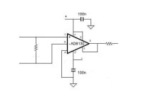
I'm illiterate when it comes to this stuff, but perhaps I could help with the diff to SE conversion stage. Some time ago I had tested AD8130 INA https://www.google.com/url?sa=t&rct...129_8130.pdf&usg=AOvVaw3-lNNeC8EmhNXJyKhtHu6Y as the input buffer in my soundcard and the reason it didn't make it was noise, something that I guess it doesn't matter here. Otherwise it was great to take 100k balanced attenuator at the input -not attached to ground.
I'm illiterate when it comes to this stuff, but perhaps I could help with the diff to SE conversion stage. Some time ago I had tested AD8130 INA https://www.google.com/url?sa=t&rct...129_8130.pdf&usg=AOvVaw3-lNNeC8EmhNXJyKhtHu6Y as the input buffer in my soundcard and the reason it didn't make it was noise, something that I guess it doesn't matter here. Otherwise it was great to take 100k balanced attenuator at the input -not attached to ground.
Attachments
Thank's for all the suggestion's guy's, appreciate it !
I have all them suggestion's on my mind when further development is happening 😉
The circuit I'am showing is with just 1/2 of the resistor divider, it shall accept balanced input also.
So the OPA1656 will ofcause also be connected to both +in and -in, choosing to GND for SE at the input.
The overall plan for this "autoranger" will be as flg. :
[INPUT bal/SE] ---> [Attenuator -0, -10, -20 or like] ---> [input protection] ---> [Sense circuit] ---> [Amplifier to raise voltage if needed with digipot / opamp MCP42010] --->
[Output sense circuit] ---> [Output SE/Bal.]
Everything controlled with a ESP32 Devkit V1 (Arduino programmed)
Right now I'am doing some "logic" coding to control the resistor divider's, after I finally got the OPA1656 / Active rectifier to behave as I would like.
Jesper.
If I understand correctly, conversion from balanced to SE is to simplify the attenuator, i.e. less relays? Keep in mind that if this will be the path for the measured signal, performance will be degraded. In any case you should not have any active circuit before the input protection. Besides, is it going to be stereo? Because if it is mono, then the relays needed are the same for a balanced attenuator given they usually have pairs of contacts.So why not [balanced attenuator] > [input protection] > [balanced soundcard input] and then steal signal from one phase of the attenuator to drive the sensor circuit?
It's actually a smart solution MagicBus...
I will consider all theese good suggestion's as I wrote before. 👍
But maybe I will get wiser along the journey, let's see...
I actually just realized that I better have in mind the attenuator circuit to not feed the rest of the circuit with more than 1Vrms to allway's have the possibility to raise the voltage to best soundcard input level that is.
Well I can do that in the programming, but the divider's also should be optimised for this.
But I did not design any "real" circuit now, so anything is possible.
The autoranger or more like if I success, will be balanced / SE and not stereo.
The name should ofcause include some kind of SuperPlayer, SuperAutoRanger (hehehe... )
Right now, and during the sommer (let's see how that will be in DK this year 🙄 ) I will test and try out the differen't solutions I have from here and in my mind.
This is e.g. also the use of the digipot. MCP42010 to set the output level in 256 step's to have excatly what is wanted, I don't know if it's possible, or if noise/THD+N will prevent this? - Anyway I will try to draw a better "block" diagram later to show here, to better understand what I excatly have in mind.
Jesper.
I will consider all theese good suggestion's as I wrote before. 👍
This is also what I thought, so I will not do this at least for now.If I understand correctly, conversion from balanced to SE is to simplify the attenuator, i.e. less relays? Keep in mind that if this will be the path for the measured signal, performance will be degraded. In any case you should not have any active circuit before the input protection.
But maybe I will get wiser along the journey, let's see...
I actually just realized that I better have in mind the attenuator circuit to not feed the rest of the circuit with more than 1Vrms to allway's have the possibility to raise the voltage to best soundcard input level that is.
Well I can do that in the programming, but the divider's also should be optimised for this.
But I did not design any "real" circuit now, so anything is possible.
The autoranger or more like if I success, will be balanced / SE and not stereo.
The name should ofcause include some kind of SuperPlayer, SuperAutoRanger (hehehe... )
Right now, and during the sommer (let's see how that will be in DK this year 🙄 ) I will test and try out the differen't solutions I have from here and in my mind.
This is e.g. also the use of the digipot. MCP42010 to set the output level in 256 step's to have excatly what is wanted, I don't know if it's possible, or if noise/THD+N will prevent this? - Anyway I will try to draw a better "block" diagram later to show here, to better understand what I excatly have in mind.
Jesper.
Coding is taking all my time right now, testing different techniques for the autoranging.
There aren't much code to look for on the net, witch can be usefull for autoranging, so I'am doing most from scratch, but it's okay, it's fun and I'am not in rush 🙂
Anyway I want to share a spreadsheet I created for the easy calculating of the dividers.
Finding it usefull.
Jesper.
There aren't much code to look for on the net, witch can be usefull for autoranging, so I'am doing most from scratch, but it's okay, it's fun and I'am not in rush 🙂
Anyway I want to share a spreadsheet I created for the easy calculating of the dividers.
Finding it usefull.
Jesper.
Attachments
Yesterday I learned about the Lm3915 and I ordered a few for a test. Less worrying about managing the input voltage in my case and we could measure the output directly without worrying about amp gain. Leaving aside dividing the voltage, datasheet says "Input Withstands ±35V without Damage or False Outputs".
We can use the reference (0dB) for a hard limit interrupting the signal and use 10 resistances to read discrete values with 3dB resolution from the output with an ADC.
Not sure if it's elegant, but I find it interesting. And we can get the LEDs for free.
Related post.
We can use the reference (0dB) for a hard limit interrupting the signal and use 10 resistances to read discrete values with 3dB resolution from the output with an ADC.
Not sure if it's elegant, but I find it interesting. And we can get the LEDs for free.
Related post.
Interesting and possible solution. You can replace led's with optocouplers and get voltage levels info safe way to mcu . Or you can try pullup mcu inputs with 10K and pass through diodes to lm3915 outputs , place resistors in place of leds ( don't remember now if lm is pulling down leds cathode to ground ).
don't remember now if lm is pulling down leds cathode to ground
Yes, I missed this.
If led supply voltage can differ from main lm3915 voltage , probably just pull-up outputs with resistor and no diodes needed. Inverted logic in code .
I really like all the suggestion's and idea's & tip's comming here!
I did some programming, and I got some pre. autoranging working on my protoboard 🙂
I took a video of the stuff...
SuperRanger
Only some simple code for now, but needed to see if I could figure it out from scratch.
Idea is to levelshift from 300/800mV and then amplify to desired voltage afterwards.
Jesper.
Nice. I'll try using a X9c103s for level control, I just ordered a few. I was reading it can store a value that is used when the chip starts. So I'm wondering if instead of using a rele one could just reset the chip to make the volume go to a safer value and ramp up from there. I don't know if it will cause a popping sound.
I just checked X9c103s datasheet ,some data in datasheet sounds strange . There's mentioned +-4V voltage ,from viper to LO and HI ,and that this is not a voltage potential , but later specified +-8V from VSS . Also THD figure is unimpressive , not for good sound applications .I think this ic is good if used as programmable voltage reference , in example in universal battery chargers to set max battery voltage by selected battery type .
Hi...
I think I need some advice.
I have setup the attached schematic on some protoboards, and it's working as expected more or less.
I also tried connecting my Behringer soundcard at the output to see if it would send a sine through it, it's working fine, allthrough it's not pretty noisewise ofcause. - But it's working.
I have the code with hysteresis working partly also, the ESP32 is sooo fast, it's nice to deal with. (I attached a video in previous post)
Looking at the schematic, please don't mind the extra part's and the wrong resistor values in the input -0dB -> -40dB attenuator part.
Also note that I use the ESP32 internal ADC now for my code, but I decided to buy an external one as suggested at first page of this thread.
So right now I'am waiting for a protoboard with 16bit ADS1115 ADC. -Reason is, that allthrough it's working fairly well, I need big hysteresis and so, for dealing with the noisy and a bit flickery non linear ESP32 ADC input's.
Schematic short explanation :
Input through -0dB to -40dB attenuator depending on the amplitude of the signal.
Diff. to SE conversion with an OPA1656, and next into an active rectifier feeding the 1. ADC.
At the same time the signal is feed into another OPA1656 witch amplifies the signal through the resistor string to give disired output amplitude.
This is feed into another active rectifier and into 2. ADC.
The input on the 1. ADC and the 2. ADC is used in the code to control the relay's ofcause.
So, what I need advices for is the following quistions...
1. Is it enough to short the lower input to GND to choose between SE or Balanced input, or do I need additional stuff to deal with this?
2. Do I need a dedicated balanced to SE conversion at the output also?

3. Do i miss some decoubling at the opamp's beside the decoubling i have at theyr'e powersupply pins.?
All advise is gladly taken ofcause...
I really hope for some good hint's 🙂
Jesper.


I think I need some advice.
I have setup the attached schematic on some protoboards, and it's working as expected more or less.
I also tried connecting my Behringer soundcard at the output to see if it would send a sine through it, it's working fine, allthrough it's not pretty noisewise ofcause. - But it's working.
I have the code with hysteresis working partly also, the ESP32 is sooo fast, it's nice to deal with. (I attached a video in previous post)
Looking at the schematic, please don't mind the extra part's and the wrong resistor values in the input -0dB -> -40dB attenuator part.
Also note that I use the ESP32 internal ADC now for my code, but I decided to buy an external one as suggested at first page of this thread.
So right now I'am waiting for a protoboard with 16bit ADS1115 ADC. -Reason is, that allthrough it's working fairly well, I need big hysteresis and so, for dealing with the noisy and a bit flickery non linear ESP32 ADC input's.
Schematic short explanation :
Input through -0dB to -40dB attenuator depending on the amplitude of the signal.
Diff. to SE conversion with an OPA1656, and next into an active rectifier feeding the 1. ADC.
At the same time the signal is feed into another OPA1656 witch amplifies the signal through the resistor string to give disired output amplitude.
This is feed into another active rectifier and into 2. ADC.
The input on the 1. ADC and the 2. ADC is used in the code to control the relay's ofcause.
So, what I need advices for is the following quistions...
1. Is it enough to short the lower input to GND to choose between SE or Balanced input, or do I need additional stuff to deal with this?
2. Do I need a dedicated balanced to SE conversion at the output also?
3. Do i miss some decoubling at the opamp's beside the decoubling i have at theyr'e powersupply pins.?
All advise is gladly taken ofcause...
I really hope for some good hint's 🙂
Jesper.
- Home
- Design & Build
- Equipment & Tools
- "Sense" circuit for MCU ADC (STM32 / ESP32 / Arduino etc...)