
Yes @TungstenAudio I know commercial Aleph doesn’t have one but just by OCD with high offset otherwise I actually don’t use any in my SIT amp
Rubber is for sissies.
Final values for 50% Aleph CCS modulation using Zen Mods AJ boards, is 950R for R24.
Given 0R27 CCS source resistor, no source resistor for SS, and 100R between JFET drains and SS gate.
Cockroaches are smiling.
Final values for 50% Aleph CCS modulation using Zen Mods AJ boards, is 950R for R24.
Given 0R27 CCS source resistor, no source resistor for SS, and 100R between JFET drains and SS gate.
Cockroaches are smiling.
Just realized I missed D1 the 9.1v zener diode in my mouser order. The closest I have in my stash is a 8.2v one. Anyone know if that will work ok?
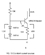
From papa's diyopamp article....
"Fig. 15b shows the current sources as made with Bipolar devices. In
this case, the bipolar transistor forming the current source is driven by
bias voltage created using a pair of diodes. The diodes drive the base
of the transistor with about 1.3 volts, and the Base to Emitter junction
drops about half of that, leaving about .65 volts left over to determine the
current through the Emitter resistor of the current source. The current
coming out of the Collector will be relatively constant at .65/R."
With this new found knowledge, run the math and calculate the collector current with the stock values shown on the schematic (9.1V minus .65V=8.45V, 8.45V divided by 1,000 ohms= .00845A (8.45mA)
Now run the numbers again with your "new" 8.2V zener to see what happens to the collector current. (hint - there's not a huge difference)
Attachments
Yes. And about half that current flows through Q1A, and the other half through Q1B in a long tailed pair.
And you can play with the numbers a little bit. Just think if the emitter resistor could be changed to something other than 1,000 ohms..... what if it was say... 910 ohms instead? What would that do to the collector current with this new 8.2V zener?
And you can play with the numbers a little bit. Just think if the emitter resistor could be changed to something other than 1,000 ohms..... what if it was say... 910 ohms instead? What would that do to the collector current with this new 8.2V zener?
So collector current would go to something around 8.3ma which is very close to the 8.45 value. So change R8 to 910 ohms.
If you wanted to stay near the design value, sure. It was a teachable moment and you quickly got the hang of it. I believe your 8.2V zener would work fine without any other changes, really. I guess it comes down to how much sleep you are going to lose over it, or not... (I probably wouldn't lose any)
To optimize sleep quality, I'd stick to the 1k resistor and include the 9V Zener with the next Mouser order. This plan would give me enough relaxation to start with the 8.2V Zener and then quickly forget about it and leave it there 🙂
... or you could research the Zener diode noise, and then choose 2 low-voltage Zener diodes that exhibit the breakdown with the true Zener mechanism. Going even further in the right direction, in general, low voltage and higher currents will give you lower noise still...
If you stay below 6.2V Zener voltage, you're good. So, a combination of 2 where each is lower than 6.2V, will be a pretty good option.
Or, use LEDs as Zeners... find the forward voltage of different types of LEDs; the white and blue LEDs have the highest forward voltage..?? Many options will yield much lower noise than a single "high voltage" Zener.
C4 is there to help with the zener noise, although I question how effective that really is. I had this 3X 3.3V series zener arrangement for awhile as a reference. Never felt like a dealbreaker either way though. I would suspect NP has a massive stockpile of those 9.1V guys in his parts room....
Attachments
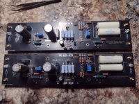
@gsrchrisu Looking good in black!
For unbalanced input you would need a jumper under -IN
For balanced input use a jumper (or zero Ohm resistor) in place of HBR/R24 and no jumper under -IN
For unbalanced input you would need a jumper under -IN
For balanced input use a jumper (or zero Ohm resistor) in place of HBR/R24 and no jumper under -IN
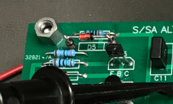
Up and running, nothing like a drama free startup. Jfets from punk dawg. Offset easily zeroed, bias set at 400mv no temps checked yet. Sounds surprisly good, I see why everyone praises it. Thanks for the Gerber's, wouldn't have tried building it otherwise.
Attachments
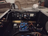
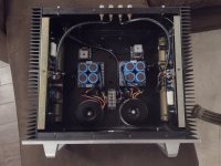
Very nice build! Where did you get your power switch? I’ve seen similar ones but they are usually only rated for 12v to 24v DC, or not more than 1A at 120v.Finally done and it’s playing music 👍
I may need to add a speaker protection module as the offset jumps above 1V when switched off and with FE22 having no caps do not want to risk my klipsch
View attachment 1303508
View attachment 1303509
View attachment 1303510
From Aliexpress - https://www.aliexpress.us/item/2255...zw2lA6U2&utparam-url=scene:search|query_from:Very nice build! Where did you get your power switch? I’ve seen similar ones but they are usually only rated for 12v to 24v DC, or not more than 1A at 120v.
- Home
- Amplifiers
- Pass Labs
- Semisouth Aleph J?