Hi!
I don't recollect where I saw it, so unfortunately I can't link to it:
I once saw a picture of a finished board, where the resistors were wonderfully elevated something between 1 - 2 mm. Aside an advantage for temperature-issues, I guess this is mainly for aesthetics.
how is this done?
Soldered from the frontside with some support under every part? (I can't imagine any other way, but this seems to be quite a finicky burdensome job...)
Thanks for any tips!
best
david
As I know in industry it is done with some flat spacer, for example some piece of heat-resistant plastic, etc. Or a holder (adaptor), like especial crocodile. (It is especial for every part).
As for me I did that with my hands (yes, I have very thick trained skin there 🙂 ). Now I don't - it was old fashion. Actual fashion is to put parts directly onto the PCB.
As for me I did that with my hands (yes, I have very thick trained skin there 🙂 ). Now I don't - it was old fashion. Actual fashion is to put parts directly onto the PCB.
Last edited:
Like in the attached image you mean?
These look soldered from the front side.
Precisely like this!
I just love that look...
As I know in industry it is done with some flat spacer, for example some piece of heat-resistant plastic, etc.
As for me I did that with my hands (yes, I have very thick trained skin there 🙂 ). Now I don't - it was old fashion. Actual fashion is to put parts directly onto the PCB.
I won't do it by hand (my poor princess' skin is way too precious :-D ) but I'll see if I can tinker something... or find another way...
THANKS!
I usually use a flat wooden stick, like the ones found in ice creams.
You can also use a thin piece of aluminium.
Anything that fits and you can remove it after soldering.
Good technique for bias resistors which generate a lot of heat, like in amplifier power stages.
You can also use a thin piece of aluminium.
Anything that fits and you can remove it after soldering.
Good technique for bias resistors which generate a lot of heat, like in amplifier power stages.
I use a folded piece of paper. I can easily adjust the width and thickness (and thus the height). Plus it has a little "give" to it so the resistors settle flatter. No fires yet 😀.
Now I don't - it was old fashion. Actual fashion is to put parts directly onto the PCB.
Now we have solder-mask to prevent shorts to the traces too, which may be a factor, and most circuitry doesn't have to worry about heat dissipation from its resistors.
take a look at the build guide for the noir headphone amp in the store. it shows pencils being used to elevate the resistors. easy to get it consistent.
Small ceramic standoff separators are available for very hot components such as ceramic wirewound resistors:
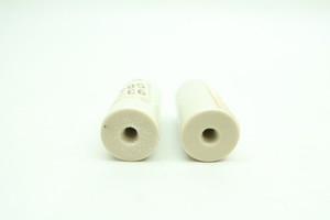


or you can use small metallic tubes, if available.
These look like spare octal pins:

or you can use small metallic tubes, if available.
These look like spare octal pins:
Ain‘t that great?
I drop in and ask about something I thought was aesthetics, and get a whole bag full of tips and techniques pointing much further!
This is so cool!
happy
David
I drop in and ask about something I thought was aesthetics, and get a whole bag full of tips and techniques pointing much further!
This is so cool!
happy
David
When I see the octal pins Juan shows, I always thought they were male Molex 09 pins. Peavey used a ton of them on amp boards.
Just find something the thickness you want and stick it under the resistor while soldering, simple really.
> When I see the octal pins Juan shows
Yeahbut.... Octal pins don't neck-down like that. I lean to your Molex identification (if not something older). Of course in this crowd "Octal" gets the idea over quickly.
Yeahbut.... Octal pins don't neck-down like that. I lean to your Molex identification (if not something older). Of course in this crowd "Octal" gets the idea over quickly.
if the resistors need to be mounted up in the air then the resistor wattage is wrong.
the trick is to not run components at their rated wattage but allow some headroom.
this increases reliabilty.
with resistor up in the air if it overheats and melts soider it will drop through pcb and maybe short out on chassis
the trick is to not run components at their rated wattage but allow some headroom.
this increases reliabilty.
with resistor up in the air if it overheats and melts soider it will drop through pcb and maybe short out on chassis

modern fibreglass pcb's will stand the heat ok.
the older cheaper type could go black or burst into flames if resistor over heated.
but shouldnt at normal working temperatures.
i prefer running resistors at below 100 degrees c
if they are above that i would increase wattage or double up to improve life of components.
the older cheaper type could go black or burst into flames if resistor over heated.
but shouldnt at normal working temperatures.
i prefer running resistors at below 100 degrees c
if they are above that i would increase wattage or double up to improve life of components.
Agreed, we can design green as hobbyists but still in the tube world many use resistors to drop voltages as old habits don't die.
Maybe they are !!!! 😛When I see the octal pins Juan shows, I always thought they were male Molex 09 pins. Peavey used a ton of them on amp boards.
I´ll have to defer to your experienced opinion 🙂
My pictures were found online after searching for "component standoff" and don´t claim ownership over them 😛
Last edited:
I use these; CHP PNR-30-D Lead Forming Pliers (Hakko)
They allow me to elevate components from boards without the need for spacers.
"C" shape forming tools
They allow me to elevate components from boards without the need for spacers.
"C" shape forming tools
- Home
- Design & Build
- Construction Tips
- self answered (maybe) question about solder-technique