To start, if you're aware of other threads/links on this subject please feel free to reference.
Backstory: Since joining this forum years ago and learning hornresp, I've played around with hundreds of combinations of subwoofer designs and speakers in hornresp and it has become one of my favorite ways to burn time. It's not uncommon for me to see a driver, lookup the T/S parameters, plug into hornresp and see if I can make a box with the flattest response curve between 40-100hz.
Example: Eminence Legend BP 102 in a ported box vs TH smoothed with a 2mh inductor in series

When I swap out the Eminence Legend driver with a JBL GT5-10D, everything goes crazy:

There doesn't seem to be much I can do with the TH dimensions in the GT5-10D to flatten it out. Therefore it seems this driver just isn't suitable for a TH unless I'm really doing something wrong here (I do want to know).
If this is not a mistake on my part, I'd really like to understand why this is happening.
I'd also like to hear any opinions on using the Legend BP 102 in a TH. These dimensions seem very reasonable and easy to build, especially if I build a TH with only one turn. I'm not concerned with maximum power (I see it will reach xmax with ~50 watts), just something with good response that is not too big and easy to build.
Settings for the Legend BP 102TH:

Bass reflex:

Settings for JBL GT5-10D TH:

Bass reflex:

Backstory: Since joining this forum years ago and learning hornresp, I've played around with hundreds of combinations of subwoofer designs and speakers in hornresp and it has become one of my favorite ways to burn time. It's not uncommon for me to see a driver, lookup the T/S parameters, plug into hornresp and see if I can make a box with the flattest response curve between 40-100hz.
Example: Eminence Legend BP 102 in a ported box vs TH smoothed with a 2mh inductor in series
When I swap out the Eminence Legend driver with a JBL GT5-10D, everything goes crazy:
There doesn't seem to be much I can do with the TH dimensions in the GT5-10D to flatten it out. Therefore it seems this driver just isn't suitable for a TH unless I'm really doing something wrong here (I do want to know).
If this is not a mistake on my part, I'd really like to understand why this is happening.
I'd also like to hear any opinions on using the Legend BP 102 in a TH. These dimensions seem very reasonable and easy to build, especially if I build a TH with only one turn. I'm not concerned with maximum power (I see it will reach xmax with ~50 watts), just something with good response that is not too big and easy to build.
Settings for the Legend BP 102TH:
Bass reflex:
Settings for JBL GT5-10D TH:
Bass reflex:
The T/S-parameters of the JBL and Eminence are quite different, so it only makes sense that they need different TH parameters as well. A bass guitar driver vs a typical car audio driver (just look at the Qts and vas).
The JBL will benefit from a higher compression ratio or smaller S1 + S2 + S3, it will also smoothen out using Vtc/ Atc (something near Vas probably).
The JBL will benefit from a higher compression ratio or smaller S1 + S2 + S3, it will also smoothen out using Vtc/ Atc (something near Vas probably).

T/S Explained: https://audiojudgement.com/thiele-small-parameters-explained/
T/S Equations and how each one affects the others: https://audiojudgement.com/thiele-s...ydc8i*_ga*MTU0NDc0NTAyLjE2ODY3OTc2NTI.*_up*MQ..
T/S max flat alignment:
Vented net volume (Vb) (L) = 20*Vas*Qts'^3.3 (Ft^3 = (Vb)/~28.31685)
Vented box tuning (Fb) (Hz) = 0.42*Fs*Qts'^-0.96
F3 (Hz) = Fs*0.28*Qts'^-1.4
(Qts'): (Qts) + any added series resistance (Rs): http://www.mh-audio.nl/Calculators/newqts.html
From this we see that until Vas is quite large, Qts' dominates.
It's not uncommon for me to see a driver, lookup the T/S parameters, plug into hornresp and see if I can make a box with the flattest response curve between 40-100hz.
The new just-released bass reflex loudspeaker design tool can make the task a little easier for vented enclosures, and sometimes produces a better result. For example, the design tool produces the following result using the Legend BP 102 driver parameter values, albeit with a larger enclosure:
Thank you. I understand the drivers are very different and I have spent time looking at what the different t/s parameters mean. My question came from the observation that the Emenence speaker can make a good TH and a bass reflex. If I put the JBL in the bass reflex cabinet, it's still a suitable response. Sure it's not the same but it still works. That's specifically what I'm trying to understand, why the JBL has so much trouble in that TH cabinet but does just fine in the reflex cabinet. I'll check out those links before following up.
change the shape of the ‘tapped horn/pipe‘ from an Expanding path to tapering or straight? Kind of like a long skinny bass reflex/TL
tune it below Fs so it doesnt spike/underdamp/bulge around Fb??
the driver ‘damping’ and the resonator shape ‘damping’ seem to require different shapes and Fb @, or below, Fs to avoid the freq responses that spike/underdamp(I think)?
in car audio drivers with more and more super tight Suspensions this is increasingly frustrating😥. Everything goes nuts at resonance and nothing else .. yuck
Last edited:
Right, a good 'rule of thumb' (ROT): https://www.diyaudio.com/community/...uild-with-some-more-bass.355384/#post-6227208
Man. I have to admit I'm exhausted trying to find ways for this to make sense. I got my degree in physical science so I'm trying to conceptually understand what is happening at a more fundamental level.
This GT5-10D just can't seem to be tamed in a TH. The below abomination is the closest I can get to anything resembling a decent response, it seems ok until it gets close to 100hz. Nothing I do gets rid of that second spike:


The reflex designer won't work with the GT5-10D because the QTS is greater than .56

Although I did the best I could and if I run them both to xmax the reflex box still seems to be the only reasonable choice.


Then a few minutes before writing this post I started thinking there may be some issues with the driver specs. This thing is supposed to have dual 4 ohm voice coils so it can be run in either 2 or 8ohm mode, but the Re is listed as 1.8ohms and the Le as 1.1mH. I doubled these values assuming it was citing 1 coil and I needed to put them in series. But if they are citing both coils in parallel then I'd have to quadruple both of these values, right? And if I do that, both boxes go completely bonkers.
I thought I'd cross reference the GT5 specs with some other similar JBL drivers (Club 1024) but this only confused me more, it's showing the 4ohm version as having a substantially lower inductance. So now I'm questioning whether all this work was wasted because not I'm not even sure what values I should be working with. A lot of the reason I picked JBL and Eminence was because I thought I could trust their measurements.
I almost didn't post here because I know you guys are experts and I barely feel like I can ask a question, but I feel like there is a learning opportunity here and I don't want to miss it.
This GT5-10D just can't seem to be tamed in a TH. The below abomination is the closest I can get to anything resembling a decent response, it seems ok until it gets close to 100hz. Nothing I do gets rid of that second spike:
The reflex designer won't work with the GT5-10D because the QTS is greater than .56
Although I did the best I could and if I run them both to xmax the reflex box still seems to be the only reasonable choice.
Then a few minutes before writing this post I started thinking there may be some issues with the driver specs. This thing is supposed to have dual 4 ohm voice coils so it can be run in either 2 or 8ohm mode, but the Re is listed as 1.8ohms and the Le as 1.1mH. I doubled these values assuming it was citing 1 coil and I needed to put them in series. But if they are citing both coils in parallel then I'd have to quadruple both of these values, right? And if I do that, both boxes go completely bonkers.
I thought I'd cross reference the GT5 specs with some other similar JBL drivers (Club 1024) but this only confused me more, it's showing the 4ohm version as having a substantially lower inductance. So now I'm questioning whether all this work was wasted because not I'm not even sure what values I should be working with. A lot of the reason I picked JBL and Eminence was because I thought I could trust their measurements.
I almost didn't post here because I know you guys are experts and I barely feel like I can ask a question, but I feel like there is a learning opportunity here and I don't want to miss it.
This math has no Qts limits:
T/S max flat alignment:
Vented net volume (Vb) (L) = 20*Vas*Qts'^3.3 (Ft^3 = (Vb)/~28.31685)
Vented box tuning (Fb) (Hz) = 0.42*Fs*Qts'^-0.96
F3 (Hz) = Fs*0.28*Qts'^-1.4
T/S max flat alignment:
Vented net volume (Vb) (L) = 20*Vas*Qts'^3.3 (Ft^3 = (Vb)/~28.31685)
Vented box tuning (Fb) (Hz) = 0.42*Fs*Qts'^-0.96
F3 (Hz) = Fs*0.28*Qts'^-1.4
When I posted I took it for granted that based on the examples listed that none referred to a TH, TP, TTL, so not 'wedded' to any taper other than what its driver specs dictates.Right, a good 'rule of thumb' (ROT): https://www.diyaudio.com/community/...uild-with-some-more-bass.355384/#post-6227208
Note too that to the 1st approximation all types of cab alignments are embedded in the post #9 math.
ID = 54.10
Comment = NEW RECORD - NEW RECORD - NEW RECORD - NEW RECORD - NEW RECORD - NEW RECORD
|RADIATION, SOURCE AND MOUTH PARAMETER VALUES:
Ang = 2.0 x Pi
Eg = 2.00
Rg = 0.00
Clo = 0.00
|HORN PARAMETER VALUES:
S1 = 700.00
S2 = 700.00
Par = 70.00
F12 = 0.00
S2S = 700.00
S3 = 700.00
Par = 65.00
F23 = 0.00
S3S = 175.00
S4 = 175.00
Par = 65.00
F34 = 0.00
S4S = 175.00
S5 = 175.00
Par = 0.01
F45 = 0.00
|TRADITIONAL DRIVER PARAMETER VALUES:
Sd = 346.00
Bl = 13.78
Cms = 1.52E-04
Rms = 3.63
Mmd = 169.70
Le = 2.20
Re = 3.60
OD = 1
|ADVANCED DRIVER PARAMETER VALUES FOR SEMI-INDUCTANCE MODEL:
Re' = 0.00
Leb = 0.00
Le = 0.00
Ke = 0.00
Rss = 0.00
|ADVANCED DRIVER PARAMETER VALUES FOR FREQUENCY-DEPENDENT DAMPING MODEL:
Rms = 0.00
Ams = 0.00
|PASSIVE RADIATOR PARAMETER VALUE:
Added Mass = 0.00
|CHAMBER PARAMETER VALUES:
Vrc = 0.00
Lrc = 0.00
Ap = 175.00
Lpt = 0.01
Vtc = 0.00
Atc = 0.00
Acoustic Path Length = 18.9
|MAXIMUM SPL PARAMETER VALUES:
Pamp = 100
Vamp = 25
Iamp = 4
Pmax = 1700
Xmax = 16.5
Maximum SPL Setting = 3
|ABSORBENT FILLING MATERIAL PARAMETER VALUES:
Fr1 = 0.00
Fr2 = 0.00
Fr3 = 0.00
Fr4 = 0.00
Tal1 = 100
Tal2 = 100
Tal3 = 100
Tal4 = 100
|ACTIVE BAND PASS FILTER PARAMETER VALUES:
High Pass Frequency = 0
High Pass Slope = 1
Low Pass Frequency = 0
Low Pass Slope = 1
Butterworth High Pass Order = 1
Butterworth Low Pass Order = 1
Linkwitz-Riley High Pass Order = 2
Linkwitz-Riley Low Pass Order = 2
Bessel High Pass Order = 1
Bessel Low Pass Order = 1
2nd Order High Pass Q = 0.5
2nd Order Low Pass Q = 0.5
4th Order High Pass Q = 0.5
4th Order Low Pass Q = 0.5
Active Filter Alignment = 1
Active Filter On / Off Switch = 1
|PASSIVE FILTER PARAMETER VALUES:
Series / Parallel 1 = S
Series / Parallel 2 = S
Series / Parallel 3 = S
Series / Parallel 4 = S
|EQUALISER FILTER PARAMETER VALUES:
Band 1 Frequency = 0
Band 1 Q Factor = 0.01
Band 1 Gain = 0.0
Band 1 Type = -1
Band 2 Frequency = 0
Band 2 Q Factor = 0.01
Band 2 Gain = 0.0
Band 2 Type = -1
Band 3 Frequency = 0
Band 3 Q Factor = 0.01
Band 3 Gain = 0.0
Band 3 Type = -1
Band 4 Frequency = 0
Band 4 Q Factor = 0.01
Band 4 Gain = 0.0
Band 4 Type = -1
Band 5 Frequency = 0
Band 5 Q Factor = 0.01
Band 5 Gain = 0.0
Band 5 Type = -1
Band 6 Frequency = 0
Band 6 Q Factor = 0.01
Band 6 Gain = 0.0
Band 6 Type = -1
|STATUS FLAGS:
Auto Path Flag = 0
Lossy Inductance Model Flag = 0
Semi-Inductance Model Flag = 0
Damping Model Flag = 0
Closed Mouth Flag = 1
Continuous Flag = 0
|OTHER SETTINGS:
Filter Type Index = 0
Filter Input Index = 0
Filter Output Index = 0
Filter Type = 2
MEH Configuration = 0
ME Amplifier Polarity Value = 1
I'm sorry but I don't have the background to consume the information in the latest posts. I feel if I knew enough to understand these responses you're providing, I wouldn't need to ask the question in the first place.
Would it be possible to try and remember back before you guys obtained the knowledge you have now? And try to speak to yourself back then? What would you say in that situation?
If nothing else, may I request assistance in verifying I'm inputting the Le and Re correctly for this driver if I use it in 8ohm mode?
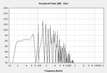
Would this be considered an acceptable response? 20-70hz seems to be a weird goal. No production subwoofers I've found have this type of range. I'm usually expecting a subwoofer to become efficient at 40hz and maintain a relatively even pressure up to 100hz at least. Since this would be for a small system, like a home theater, the tops usually can't go much lower than 100hz. I see a lot of people design boxes to be efficient down to 20hz but I don't understand why you'd want to do that if it means you're sacrificing efficiency up in the audible range.1st approximation for a GT5-10D tapped alignment (faded is with Le, thermal power distortion).
Anyway, aside from that, I think I'm understanding you're showing me the math that would give me an ideal response without using hornresp. I do appreciate that, but the reason for my post is to better understand what about this specific driver makes it go crazy in a TH. I see you guys are taking my Le and Re values but I really don't think it's possible for these to be correct. 3.6 ohms for an 8 ohm speaker just doesn't seem right. And if that's not right, then none of this math is going to help.
Ok I just noticed they are saying the coils are in parallel. So 1 coil by itself is 3.6 ohms and 2.2mH, correct? Then if we put the coils in series it should work out to be 7.2 ohms and 4.4mH? This gives us a vastly different response.
So if nothing else, I've learned that if you build a box for a driver with dual voice coils, you need to re-engineer the box if you want to change it from series to parallel and vice versa. And it also shows all our previous sims are invalid.

So if nothing else, I've learned that if you build a box for a driver with dual voice coils, you need to re-engineer the box if you want to change it from series to parallel and vice versa. And it also shows all our previous sims are invalid.
Understood and why I've mostly posted tech info to educate, but guessing here that you (or at least some lurkers) need to start at 'square one', so..........
T/S Explained: https://audiojudgement.com/thiele-small-parameters-explained/
T/S Equations and how each one affects the others: https://audiojudgement.com/thiele-s...ydc8i*_ga*MTU0NDc0NTAyLjE2ODY3OTc2NTI.*_up*MQ..
........then move on to resonant pipe theory and once you've 'grokked' all this, then combine all this knowledge to begin 'having a clue' how to design a basic TH, then making numerous 'proofs of concept' to fine tune them as I did or do like most folks nowadays that just use Hornresp's ever more flexible wizards to 'slide' their way to one that they find acceptable, though even then, once built it still doesn't meet the design goals, so tweak as best they can or start over.
But to answer your 'What would you say in that situation?'; way back when I asked for advanced tech info, more often than not I was told to go get a college level physics and/or math and/or mechanical and/or electrical and/or aeronautical engineering textbook(s) and learn the same way they did, though a few did help me with the math (and folks still do to this day as it's literally 'Greek' to me) once I showed sufficient dedication to learning.
In series = 7.2 ohms, Le = 2.2 mH (see chart)......... yeah, I'm always in a hurry and/or seriously sleep deprived nowadays and wasn't paying attention beyond noticing that the driver specs from a similar JBL DVC sim had the wrong Eg (s/b 2.83 V). Kind of surprised BW didn't catch this.....
Anyway, changing to 7.2 ohms, BL doubles to 19.4 Bl, but all this does is drop eff. 3 dB, doesn't otherwise change the sim(s)........
Anyway, changing to 7.2 ohms, BL doubles to 19.4 Bl, but all this does is drop eff. 3 dB, doesn't otherwise change the sim(s)........
Attachments

For the original title: flat frequency response is not that strictly best choice anymore. I would dig deeper into the problematics to se what's up. Peaks in frequency response can mean issues, but it also means efficiency. You can sometimes just knock down the power input at that frequency by using DSP, and you are fine. It depends on what happens there.
Looking at the two drivers, I see similar fs and motor strength but the JBL has over 4x the moving mass as well as a corresponding stiffer suspension to keep the fs up.There doesn't seem to be much I can do with the TH dimensions in the GT5-10D to flatten it out. Therefore it seems this driver just isn't suitable for a TH unless I'm really doing something wrong here (I do want to know)
The following is my intuitive understanding, mostly based on playing with FLH models, and which may be incomplete/wrong:
At the impedance minima where the cone is nearly immobilized by the horn tuning, the output of either driver is similar and suspension/mass doesn't have a big effect. But further away from the impedance minima where the cone really gets moving, the motor isn't strong enough to move heavy cone + suspension + air column and you therefore lose output.
For these reasons I understood that a good horn driver needs a lighter cone or correspondingly stronger motor.
Right, T/S specs only defines/shapes the driver's response in its acceleration BW from Fs to its upper mass corner (Fhm = 2*Fs/Qts') where the driver's mass, inductance controls its response, so the JBL has a narrower gain BW due to a much lower Fhm and due to its much higher inductance, rolls off much lower in the HF.
(Qts'): (Qts) + any added series resistance (Rs)
(Qts'): (Qts) + any added series resistance (Rs)
- Home
- Loudspeakers
- Subwoofers
- Seeking a better understanding of the physics behind selecting ideal T/S parameters for a small TH