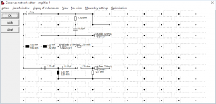
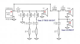
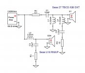
For some reason I'm drawn to the Seas Idunn kit. I've read more than a few complaints about Idunn being shy on bass and overly bright. I've also planning on doing a 2.5 speaker for myself for some time. So.. I designed an XO for a "2.5 Idunn". It's very close to the original Idunn, but adding a woofer in a parallel cascaded design in a way that shouldn't be bass shy.
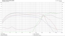
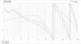
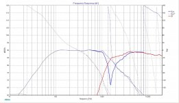
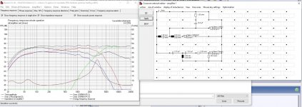
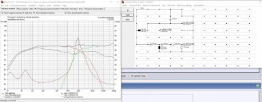
So, how do you view my idea for "Idunn 2.5"? It shouldn't leave one wanting for bass or complaining over overly bright upper frequencies. How about the XO and the phase? BoxSim models SPL at eternity or something like that, so I've tried the design on PCD7 as well to deal with the phase of drivers not adjacent. PCD7 response wasn't bad either. I'm pretty happy with the premier woofer (Stupidly driver no. 3, U18RNX/P 3, at the graphs) coinciding with the tweeter at XO point.
So, how do you view my idea for "Idunn 2.5"? It shouldn't leave one wanting for bass or complaining over overly bright upper frequencies. How about the XO and the phase? BoxSim models SPL at eternity or something like that, so I've tried the design on PCD7 as well to deal with the phase of drivers not adjacent. PCD7 response wasn't bad either. I'm pretty happy with the premier woofer (Stupidly driver no. 3, U18RNX/P 3, at the graphs) coinciding with the tweeter at XO point.
Attachments
Hi,
Typical 2.5 way problem. Try preceding both midbass drivers
with the treble x/o and then the inductor to the 0.5 way
driver, it should sort out your obvious x/o problem.
rgds, sreten.
Typical 2.5 way problem. Try preceding both midbass drivers
with the treble x/o and then the inductor to the 0.5 way
driver, it should sort out your obvious x/o problem.
rgds, sreten.
Hi,
Typical 2.5 way problem. Try preceding both midbass drivers
with the treble x/o and then the inductor to the 0.5 way
driver, it should sort out your obvious x/o problem.
rgds, sreten.
What's the "obvious xo-problem" or the "typical 2.5 problem" here?
Last edited:
What's the "obvious xo-problem" or the "typical 2.5 problem" here?
Hi,
According to your schematic there is no way driver 1 will
ever get more treble than driver 3 and I suspect that the
posted x/o is simply not the one used for the simulation.
The simulation graphs tell a different story, I described.
rgds, sreten.
Last edited:
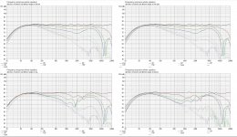
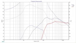
The power response surely looks bad, but the dxt-tweeter doesn't behave like a normal tweeter would. BoxSim predicts the off-axis SPL by the radius of the tweeter, but the actual DXT-tweeter behaves more like a 5 inch midrange without the 5+ kHz droop.
Hi,
According to your schematic there is no way driver 1 will
ever get more treble than driver 3 and I suspect that the
posted x/o is simply not the one used for the simulation.
The simulation graphs tell a different story, I described.
rgds, sreten.
Do you mean the driver 3 (red) getting more treble than driver 1 (blue)? The driver 3 (red) is getting all the treble at 500 Hz+. The driver 1 (blue) does 12 dB less at 2 kHz than driver 3 (red). The driver 3 (red) is the primary woofer crossing with the tweeter and driver 1 (blue) is the .5 woofer.
The series inductor for driver 1 (blue) acts as a high pass filter for driver 3 (red). The more inductance is added for driver 1 (blue) the more driver 3 (red) gets treble. If this isn't right, there's something wrong with BoxSim. For me this makes sense, however, like a shunted inductor for the tweeter or a shunted capacitor for the woofer.
Feel free to try it out though, I'll be happy to provide you with the .frd and .zma files I used (they're just SPLCopied from Seas datasheets, the reality when measured with the actual drivers might prove to be something different, but I'll handle that then).
Last edited:
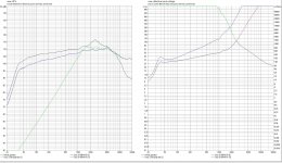
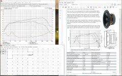
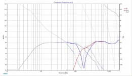
I checked if the raw driver graph seems right, especially that BoxSim doesn't add any SPL to the primary woofer (driver 3), because that would be obviously wrong. It doesn't, it only attenuates the drivers as it should. Attached: raw single woofer SPL. Seems right.
Attachments
Hi,
My apologies, I mixed up the energy response with driver response.
Still, 2R in series with a bass driver is a bad idea, will mess up Qts.
rgds, sreten.
My apologies, I mixed up the energy response with driver response.
Still, 2R in series with a bass driver is a bad idea, will mess up Qts.
rgds, sreten.
Hi,
Still, 2R in series with a bass driver is a bad idea, will mess up Qts.
rgds, sreten.
That's new information to me, thank you for pointing that out!
Do you know if the DCR of series inductors has a similar effect? Does the effect on driver Qts depend on whether series resistance is placed before or after the driver in the crossover, or before or after the series inductor of a low pass filter? Can the effect on Qts be calculated somehow?
The reason I'm using inductors with big DCR and the 2R series resistor is, firstly, because I tend to get a bit more SPL at 100-200 Hz than I'd really want to. Because woofer impedance is at its lowest at that frequency range, I guess, series resistance attenuates mainly those frequencies and gets me where i want to be SPL-wise at 100-200 Hz.
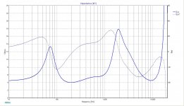
Secondly, I don't expect my cheapish Yamaha home theater amp to be able to handle 4 ohm speaker load, so I'd like to keep the lowest impedance at around or over ~6 ohms.
Is there a smarter way to achieve these goals?
Hi,
DCR of inductors has a similar effect.
mh-audio.nl - Home
Its not a problem if the correct Qts
is used for the bass alignement.
rgds, sreten.
DCR of inductors has a similar effect.
mh-audio.nl - Home
Its not a problem if the correct Qts
is used for the bass alignement.
rgds, sreten.
This was done with Seas curves in 10 litre sealed box. Impedance
was simulated separately and modified to match Seas Imp curve.
Seems a waste to lose the sensitivity of Seas midwoofers.
was simulated separately and modified to match Seas Imp curve.
Seems a waste to lose the sensitivity of Seas midwoofers.
Attachments
Hi,
DCR of inductors has a similar effect.
mh-audio.nl - Home
Its not a problem if the correct Qts
is used for the bass alignement.
rgds, sreten.
Unibox seems to be able to calculate enclosures depending how much series resistance is added.
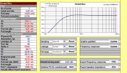
For two U18RNX/P's in parallel the driver Qts goes from 0.369 up to 0.552 if 2 ohms in total is added in series of the two parallel woofers. This would call for a ridiculous 123.7 liter reflex enclosure for two woofers, or 61.85 liters per driver respectively, tuned at 31.21 Hz. The series resistance also adds peak cone excursion a bit because of the higher Qts, even if enclosure size remains the same.
In the 61.85 liter enclosures bass response would extend to F3 of 27.4 Hz, but of course peak cone excursion is totally out of the driver's ballpark, so it's not even remotely close to doable.
Last edited:
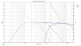
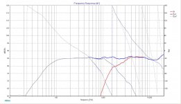
In the enclosure I was thinking about, 2 x 22 liters (22 per driver), tuned at 38 Hz it still seems doable with 2 ohms resistance. Cone excursion should stay pretty much at linear range until the tweeter power limitation. Woofer SPL isn't optimal, but it isn't too bad either. The 2 ohms I used for the simulation came from this XO I tried with smaller primary inductor (1 mH, 1.2 ohms dcr) and secondary inductor with lower dcr. I also removed the resistor
Also I noticed that the graph I used SPLCopy on, had probably a bit too narrow top octave, so my FRD file had the woofer's SPL peak at 5 kHz instead of 4 kHz where it should be. I made a new FRD that seems better aligned with the SPL graph and used it in the simulation. That caused some other minor changes in the XO.
Also I noticed that the graph I used SPLCopy on, had probably a bit too narrow top octave, so my FRD file had the woofer's SPL peak at 5 kHz instead of 4 kHz where it should be. I made a new FRD that seems better aligned with the SPL graph and used it in the simulation. That caused some other minor changes in the XO.
Attachments
Last edited:
This was done with Seas curves in 10 litre sealed box. Impedance
was simulated separately and modified to match Seas Imp curve.
Seems a waste to lose the sensitivity of Seas midwoofers.
I agree it's not very smart to make a 2.5 speaker to add bass, and then remove bass with a resistor. 😀 I tried a smaller primary inductor like in the XO you posted and removed the resistor. It seems to be working fine.
For me the 4 ohms minimum impedance is a problem, though. I know my amp can't handle it, and that's why I'd like to get a bit higher minimum impedance. 6 ohms would be great, 5 ohms is borderline. On the other hand, it might be wiser to get a better amp or not to make a parallel 2.5 in the first place. I'm kind of running circles around this idea and different options.
This design you referred to, has it been build? If so, I'm curious how it sounds?
Last edited:
My simulated design was a variation of yours. There is no doubt at
all that a real design based on these drivers has the potential of
sounding great.
What is your amplifier exactly? The impedance of my design
doesn't look that demanding at all, and you don't have to supply
the voltage that makes it unfit to drive these. 90 dB of SPL
is much for a hifi speaker.
The solution to your demand of increased impedance (5-6 ohm)
is simple. Use only one midwoofer, as Idunn is. These kind of drivers
always have higher Fs than what manufacturer suggests, this is at least
what my measurements have tought me.
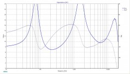
My amp is a Yamaha HTR-2064, an affordable (or cheap if you will) home theater amp. Manual says it'll handle 6 ohms. However, for the heck of it i just measured the impedance of my Boston Acoustic A25 speakers I have as surround speakers. The "8 ohm" A25 speaker apparently has it's lowest impedance at 4.39 ohms and an impedance curve somewhat resembling my "Idunn 2.5" plan.. I tried driving it quite loudly (loud enough for my home use) and there wasn't any problem at all! So you're probably right, my amp shouldn't have a problem with the dip at 4+ ohms at ~150 Hz.
I quickly simulated the original Idunn XO with the files I have, leaving .5 woofer out, and got a result that looks quite like the published Idunn measurements. I'm not that fond of the original Idunn XO by looks of the on-axis SPL, especially the constant SPL ascension towards treble, altough I haven't had a chance to listen to them. .5 woofer would let me to handle baffle step and get more bass (SPL and extension) and a flatter SPL. And a bit more sensitivity of course.
I am, however, very interested on the Idunn off axis behavior and sound power response, as well as the woofer bass extension capabilities and the woofer having no hard cone break up modes, save the 4 kHz peak at 60 degrees listening angle the woofer shows.
My current diy 2-ways (a redesign to replace broken woofers) were a nice learning experience, and sound decent, but I'm not completely happy with them. I'm also moving to a bit bigger flat soon and have been recently obsessing over 2.5 ideas for some reason.
Attachments

I can tell you that Yamaha makes a very robust amplifier section, and I would say it will handle the load on your 2.5-way. I have had a couple Yamaha's and never had a problem with 4-ohm speakers, ran 4-ohm mains and center (both dipped below 3 ohms) for 4+ years in my 20's (i.e. listened at very loud levels) and never once shut down or complained about the load. You will be fine.
Plus I want you to build this, because I really like those woofers.
Plus I want you to build this, because I really like those woofers.
Well, I'm already mentally quite committed to the idea, so I think I'll start the build after we've moved to the new flat next week. I've been looking into other drivers and designs as well, but am quite set on this design now. In the worst case scenario I'll be left with a kit to build a pair of Seas Idunn's and two extra U18RNX/P's to do something with.
For woodwork I have little more than a stone axe (I'll buy a jigsaw that can cut in 45 degree angle, a drill, and some hand tools). So, for convenience's sake I'll be making the boxes out of 18 mm thick laminated wood panels (pine) that are used for shelving and such, and therefore are readily available in handy dimensions at affordable prices. That way the amount of sawing will be at minimum. The baffle will be thicker, 28 mm I reckon at the moment.
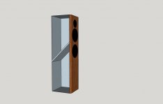
The speakers shall be 1000 mm tall, 236 mm wide and 278 mm deep (outer dimensions). Baffle edges (at least side edges) shall be filleted at about 2.5 - 3 cm radius. I'll see about the top edge when I'll get to try a spokeshave and a scraper to the panel's end grain. Might not be doable. Probably filleting even side edges with such radius is going to be quite a hard and time consuming task with hand tools. Something to do at evenings. 🙂
The enclosure I'll divide into two compartments, about 19-20 liters each with their own reflex ports. Effective volume with stuffing will be that way about 22 liters. The divider I'll make 45 degrees slanted so I can fit the drivers close to each other and still get the needed volume for the upper woofer. The slanted divider won't hurt in sense of eliminating resonance modes either. I'll probably also add one brace of some sorts per compartment. The box should end up being something like the rough sketch I enclosed.
For woodwork I have little more than a stone axe (I'll buy a jigsaw that can cut in 45 degree angle, a drill, and some hand tools). So, for convenience's sake I'll be making the boxes out of 18 mm thick laminated wood panels (pine) that are used for shelving and such, and therefore are readily available in handy dimensions at affordable prices. That way the amount of sawing will be at minimum. The baffle will be thicker, 28 mm I reckon at the moment.
The speakers shall be 1000 mm tall, 236 mm wide and 278 mm deep (outer dimensions). Baffle edges (at least side edges) shall be filleted at about 2.5 - 3 cm radius. I'll see about the top edge when I'll get to try a spokeshave and a scraper to the panel's end grain. Might not be doable. Probably filleting even side edges with such radius is going to be quite a hard and time consuming task with hand tools. Something to do at evenings. 🙂
The enclosure I'll divide into two compartments, about 19-20 liters each with their own reflex ports. Effective volume with stuffing will be that way about 22 liters. The divider I'll make 45 degrees slanted so I can fit the drivers close to each other and still get the needed volume for the upper woofer. The slanted divider won't hurt in sense of eliminating resonance modes either. I'll probably also add one brace of some sorts per compartment. The box should end up being something like the rough sketch I enclosed.
Attachments
Last edited:
- Status
- Not open for further replies.
- Home
- Loudspeakers
- Multi-Way
- Seas "Idunn 2.5"