You don't really have to put a divider in the box. Just calculate
the port for two drivers in a single cabinet voulme. I would
rather put multiple braces throughout the box and make sure
the stuffing is in the right places. 236 mm is a lot for 6,5"
midwoofers. The cabinet might look more elegant with a more
narrow baffle.
the port for two drivers in a single cabinet voulme. I would
rather put multiple braces throughout the box and make sure
the stuffing is in the right places. 236 mm is a lot for 6,5"
midwoofers. The cabinet might look more elegant with a more
narrow baffle.
You don't really have to put a divider in the box. Just calculate
the port for two drivers in a single cabinet voulme. I would
rather put multiple braces throughout the box and make sure
the stuffing is in the right places. 236 mm is a lot for 6,5"
midwoofers. The cabinet might look more elegant with a more
narrow baffle.
I ended up with 236 mm width for two reasons:
Firstly, there are 200 mm wide panels at different lengths (from 800 mm up) readily available, so when I use that width for back panel and attach side panels to its sides, I can make top and bottom panels and all the braces and dividers from that same panel width just by cutting them to right length. The 18 mm thick side panels and 200 mm wide back panel make for total width of 236 mm.
Secondly, I want to try filleting aka rounding the baffle edges to eliminate SPL peaks and dips caused by baffle diffraction. When rounded at radius of 25 mm or more, they seem to remove almost all diffraction effects above 2000 Hz (according to Bagby's Frequency modeler spreadsheet). When the baffle edges are rounded at 25 mm radius, the baffle starts curving back at 5 mm distance from woofer's edge, so I don't think it'll look too bulky (the woofers are 176 mm in diameter).
You don't really have to put a divider in the box. Just calculate
the port for two drivers in a single cabinet voulme.
I've been considering that. It would require only one port, no need to pass cables through the divider etc; just generally easier to build. If I'd be using double woofers just connected in series or parallel, I'd do that.
However, in the cascaded parallel design the .5 woofer gets more inductance than the primary woofer, which shifts its phase more than the primary woofer's phase is shifted. In simulation they get gradually out of phase above 60 Hz. The phase shift at 100 Hz is about 15 degrees and at 200 Hz it's about 20 degrees (see the first post of thread). The shift gets up to approx 40 degrees at XO point, but of course at that point the .5 woofers SPL is about 11 dB lower than the primary woofer's SPL.
The 0.5 woofer also gets more DCR than the primary woofer, 0.6 ohms or so, which raises it's Qts.
Because of the phase and Qts difference, I'm quite hesitant to put both woofers in the same chamber.
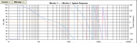
I'm not sure what you have done in your simulation to have such
driver phase response difference at low frequencies. This is how
it looks in PCD. Mic position is a tweeter axis (0 deg hor.; 0 deg vert.)
At about 165 Hz there is an anomaly in your phase graph. Have you done
any splicing here?
driver phase response difference at low frequencies. This is how
it looks in PCD. Mic position is a tweeter axis (0 deg hor.; 0 deg vert.)
At about 165 Hz there is an anomaly in your phase graph. Have you done
any splicing here?
Attachments
I'm not sure what you have done in your simulation to have such
driver phase response difference at low frequencies. This is how
it looks in PCD. Mic position is a tweeter axis (0 deg hor.; 0 deg vert.)
At about 165 Hz there is an anomaly in your phase graph. Have you done
any splicing here?
No, I haven't done any splicing. The anomaly is probably caused by BoxSim, it calculates box response from driver T/S parameters until "around 2fc", apparently in this case until 165 Hz; Woofer fc is 56.11 Hz according to BoxSim. It then splices the imported frd file (in this case copied from datasheet) to the calculated box response from that point on.
The phase was minimum phase extracted by Bagby's spreadsheet in the first post, I think. I tried now with minimum phase calculated by BoxSim from SPL (graph attached).
I don't think it differs that much from the XSim graph you posted. In your graph there's 30 degrees between two vertical rules, so the phase difference in your graph is about ~10 degrees at 100 Hz and 30 degrees at 200 Hz. In my graphs there's 10 degrees between rules, and the difference is ~10 degrees at 100 Hz and 20 degrees at 200 Hz. In your graph the difference seems to start a bit later, but your graph is vertically a bit more narrow, so the difference doesn't show so well at ~70 Hz.
Attachments
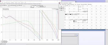
I'm not sure that BoxSim takes into account the higher Qts caused by series resistance though, for adding resistance only seems to reduce SPL where woofer impedance is at it's lowest, i.e. at ~100-200 Hz, whereas the higher Qts should cause an opposite effect. The crappy thing about BoxSim is that there isn't any documentation or official manual out there for one to check how it does things. Or at least I haven't found one.
The real XO work will start when I have the drivers and get actual measurements and see how they really behave. I wouldn't expect these simulations to be far off though.
The real XO work will start when I have the drivers and get actual measurements and see how they really behave. I wouldn't expect these simulations to be far off though.
Last edited:
And now that I think about the low frequency difference in our graphs, of course your SPL is from 10 liters closed box and mine is from 22 liters reflex box, so they're bound to be a bit different.
And you were talking about PCD, but I for some reason thought you said XSim. I don't think that should make any difference though.
Got it now. The difference was there because you calculated
with dcr of 1,6 and 1,9 along with splicing error. For dcr I was
using 0,25 and 0,5.
with dcr of 1,6 and 1,9 along with splicing error. For dcr I was
using 0,25 and 0,5.
I should really understand phase better, though! I do understand some basic consequences in XO design, i.e. sound waves in similar acoustic phase amplifying each other and sound waves in opposite acoustic phases cancelling each other out and everything in between. Also similarly electrically impedance cancelling out impedance in opposite phase, which can be used in resonance circuits and so on.
However, acoustic (minimum) phase is apparently function of SPL since it can be calculated from SPL curves. I'll probably find the function somewhere, but I don't currently understand the relationship (in lay man's terms).
Also I'm wondering how phase is connected to time behavior (or impulse response?). I'm thinking, for example, that when the 0.5 woofer is in different phase from the primary woofer, as in the simulation, could that phase difference be corrected via physical alignment, i.e. increasing or decreasing the distance to listener? I'm thinking it of course could, for phase obviously changes at a different listening distance, but how do phase, amplitude, frequency and time(/distance) interconnect? Getting philosophical after a few beers (it's 11 PM in Finland 🙂).
Well, the build will start anyway in a couple of weeks.
Last edited:
Got it now. The difference was there because you calculated
with dcr of 1,6 and 1,9 along with splicing error. For dcr I was
using 0,25 and 0,5.
I don't know if it was because of that. Too many unknowns for me. I don't know any of the functions used for these calculations nor do I know any of the source code in these programs. For me the phase of 0.5woofer deviates from the primary woofer if I make a cascaded parallel XO. If they'd be just in series or parallel, the simulation shows identical phases and SPL:s.
For now it's just about some simple decisions for me: Dividing the box into two compartments because I can't be sure how it'd work in a common enclosure, also eliminating the most obvious resonance modes. Placing the drivers vertically close together so that vertical lobing is minimized. Filleting the edges so that baffle diffraction effects are minimized.
I've lost my blind faith in simulating on datasheet basis. I'll just have to build, measure with the imperfect tools I have, simulate, adjust and finally trust my ears. 🙂
The divider makes cabinet stronger and because it is oblique it prevents box modes. .5 works well in one box but a large box has it's own problems.
The divider makes cabinet stronger and because it is oblique it prevents box modes. .5 works well in one box but a large box has it's own problems.
If you were building (these) 2.5 speakers, would you go for the 45 degree slanted divider or a single 45 liter box for both woofers?
Unfortunately, the box modes won't go away by using a slanted divider.
The frequencies will be shifted higher. There is always a need to damp
the standing waves whenever in the passband if one wants to do it right.
The frequencies will be shifted higher. There is always a need to damp
the standing waves whenever in the passband if one wants to do it right.
The original Idunn design uses 12.5 g stuffing per liter, and I think I'll follow the design there.
Box modes are caused, if I understand correctly, by standing waves that usually occur when sound waves reflect between two parallel surfaces opposing each other. The slanted divider should break vertical standing waves for there aren't parallel surfaces facing each other anymore in vertical direction. For angle of incidence = angle of departure, it could of course create an L-shaped standing wave, if such standing waves exist. The distance from bottom panel to the divider is different than the distance from the divider to baffle though. Of course lower frequencies with longer wavelength might just pass through the divider for it's just 18 mm thick.
What I'm concerned about, is the back panel parallel to the upper woofer causing a mode or a reflection that might cause a peak or a dip to appear in the woofer's response. I think I'll try to prevent that by adding a slanted and holed brace behind the upper woofer. The bottom compartment might get just a horizontal holed brace.
Last edited:
The slanted divider should break vertical standing waves for there
aren't parallel surfaces facing each other anymore in vertical direction.
Of course lower frequencies with longer wavelength might just pass
through the divider for it's just 18 mm thick.
Lower frequencies won't be passing anywhere through.
If you have any doubts about standing waves, read what Toole has written
in his book "Sound Reproduction" mentioning Dr.Geddes and his 1982
studies of the same topic.
Read also the post #74.
http://www.diyaudio.com/forums/multi-way/284239-seos-dayton-2-way-8.html
If that still won't be enough, measure yourself.
Yeah, the sound wave reflection probably has more to do with the density difference between air and wood than panel thickness. I have to admit I don't know that much about acoustics. I'll have to do some reading on the subject to have better understanding of basics.
Surely enough there are resonance modes in the air column in e.g. french horn, even the thing is wrapped around itself about twenty times. 🙂
Unfortunately, the box modes won't go away by using a slanted divider.
The frequencies will be shifted higher. There is always a need to damp
the standing waves whenever in the passband if one wants to do it right.
Now that I've given this some thought, you're absolutely right. Standing waves don't need two parallel surfaces (I don't know where that idea came from) to form, they only need two sound waves of the same frequency and phase traveling opposite directions. It doesn't matter if the waves are reflections or if they come directly from a driver. And woofers of course radiate pretty much every direction in a spherical pattern. Half of the spherical pattern goes into the box and the other half outwards (directivity of course goes up at higher frequencies narrowing the pattern or at least reducing SPL at off axis angles).
So, numerous standing waves will form into an enclosure no matter what it's shape is, only their frequencies vary. The distance the sound waves travel must be at least half of their wavelength for a standing wave to form at a given frequency. I drew a picture for myself to understand the idea, it's attached. 🙂
The longer path the sound waves have to travel, the lower is their amplitude, for stuffing absorbs their energy when they travel through it. On the other hand, longer waves (lower frequencies) carry more energy. Standing waves may leak out by exciting enclosure walls enough to make them resonate and thus emit sound outside of the box. Bracing and other damping of the enclosure prevent those vibrations, and bracing also shortens distances inside the box, so standing waves can only form at higher frequencies where their energy content is lower and thus less likely to excite walls to resonate.
Attachments

Lojzek is right - an oblique divider will not cancel modes, but it will eliminate modes in the passaband of woofers! This is the point! And besides that you will need internal bracing for support any way!
Yes, I would make the oblique divider!
Her a calculator, try it! Internal Standing Wave Calculator for Loudspeaker Enclosures and Rooms
Yes, I would make the oblique divider!
Her a calculator, try it! Internal Standing Wave Calculator for Loudspeaker Enclosures and Rooms
- Status
- Not open for further replies.
- Home
- Loudspeakers
- Multi-Way
- Seas "Idunn 2.5"