6.5k,7k, 8k is not a big deal. Exact OPT impedance depends on exact OP and exact output load. And there is no such thing as exact output load rather there is a range.
For me it is difficult to explain because one aspect relates to many others. Please consider that for now that 6.5k or 8k instead of 7k is okay. Please note data sheet OPT primary impedance comes from fixed resistor connected with secondary.
Regards
For me it is difficult to explain because one aspect relates to many others. Please consider that for now that 6.5k or 8k instead of 7k is okay. Please note data sheet OPT primary impedance comes from fixed resistor connected with secondary.
Regards
Suitable opt primary impedance for 300B se ranges from 2k to 5k as per WE application, go figure.
Regards
Regards
Yeah, I'm aware that the load impedance listed in the data sheet is not a figure set in stone and that in actual use it bounces all over the place due to the varying impedance of the speaker at different frequencies.6.5k,7k, 8k is not a big deal. Exact OPT impedance depends on exact OP and exact output load. And there is no such thing as exact output load rather there is a range.
For me it is difficult to explain because one aspect relates to many others. Please consider that for now that 6.5k or 8k instead of 7k is okay. Please note data sheet OPT primary impedance comes from fixed resistor connected with secondary.
I typically use OTs that are scrounged from other equipment so I almost never use something that matches the data sheet spec. I use whatever I have that's closest to the spec and call it a day.
The reason I ordered the Edcors is because they are more substantial (15w) and probably have a wider frequency response (especially on the low end) than the little OTs that were originally used in a Voice of Music SE 6BQ5 console amp. Whether or not they will sound any better remains to be seen. All I have to measure with is my ears.
FlaCarlie....I mostly play with DHT and TT. However I feel like trying DHT drive IDHT output and I think 6N6G is interesting. But I am disrupted by its rather high plate resistance @24K, that said it needs some kind of feedback to improve damping.
Somebody more knowledgeable in this area could help!
Regards
Somebody more knowledgeable in this area could help!
Regards
Your understanding of the technical aspects is obviously much deeper than mine.FlaCarlie....I mostly play with DHT and TT. However I feel like trying DHT drive IDHT output and I think 6N6G is interesting. But I am disrupted by its rather high plate resistance @24K, that said it needs some kind of feedback to improve damping.
Somebody more knowledgeable in this area could help!
In the PP 6N6G I built, I did add some NFB. But I don't have a scope or any way to measure it. I just do it by ear and it did tighten up the bass a bit. It didn't actually sound too bad without any but bass guitar was more defined with a bit added.
Here's a thread on that build. It's just a modded Magnavox amp that came out of an old console stereo. It's ugly but sounds great.
Magnavox 175/185 Build . . . With a Twist | Audiokarma Home Audio Stereo Discussion Forums
I'm not using any NFB with the 26 - 6N6G SET I have breadboarded. It sounds fine to me without it. I don't listen to much music that's bass heavy but when I tested it with a CD that has some pretty low and thumpy synth bass it was really solid.
Thank you FlaCharlie bhai. I have some idea about what I don't know. But I don't understand how-come a tube with 24K internal resistance sounds good even low under loaded with a 7K opt! But I trust you that it really sounds good. I will
investigate further if I dig out some fact I will let you know.
Regards
investigate further if I dig out some fact I will let you know.
Regards

Well John,
1) I expect the output triodes are transmission tubes that idle with a positve grid; and a lot of grid current (say 2-5 mA).
I gave my pair of 100TH to Peter van W. He trades valves; I did not want a transmission studio after all . .
So that explanes the output drive;
2) next the connection of the input cathode follower to the UL tap . . . There is a whole lot of thinking around so called super-triode outputs (or named different, I cannot recollect quickly enough, but bear with me); where there is a triode that is used as anode resistance of a pentode input (high Rp) where the anode is connected to the output transformer primary; the result is a feedback loop. The feedback forces a triode even while the output also is a pentode . So this connection can have a effect in the loop of really giving feedback.
3) to finalize the puzzle, the input transformer must give all the gain, say allow an output well above +26 dB. I am no certain if that input stage to the coupling transformer should be with a pair of pentodes or that the input could be a triode.
Anyway, it looks like Mr Nelson Pass gave us a new puzzle. . .
1) I expect the output triodes are transmission tubes that idle with a positve grid; and a lot of grid current (say 2-5 mA).
I gave my pair of 100TH to Peter van W. He trades valves; I did not want a transmission studio after all . .
I have used 814 in the past with a ECC88 white-cathode follower with direct coupling.
So that explanes the output drive;
2) next the connection of the input cathode follower to the UL tap . . . There is a whole lot of thinking around so called super-triode outputs (or named different, I cannot recollect quickly enough, but bear with me); where there is a triode that is used as anode resistance of a pentode input (high Rp) where the anode is connected to the output transformer primary; the result is a feedback loop. The feedback forces a triode even while the output also is a pentode . So this connection can have a effect in the loop of really giving feedback.
3) to finalize the puzzle, the input transformer must give all the gain, say allow an output well above +26 dB. I am no certain if that input stage to the coupling transformer should be with a pair of pentodes or that the input could be a triode.
Anyway, it looks like Mr Nelson Pass gave us a new puzzle. . .
Last edited:
Thank you FlaCharlie bhai. I have some idea about what I don't know. But I don't understand how-come a tube with 24K internal resistance sounds good even low under loaded with a 7K opt! But I trust you that it really sounds good. I will
investigate further if I dig out some fact I will let you know.
Regards
There I remember a strange remark: a triode that is loaded far under the Rp will behave as a pentode. The frequency domain even expands.
I once made a noval-triode that ran into an anode resitance of 1k5. Why? Well that was the loading required for a DAC output current (TDA1541 running as NOS) that entered at the cathode pin. It was marvelous. Well into the MHz - that is, the edges of the steps were all clear. My filter came after.
Thank you triode_al bhai for your interesting input. Then why we run after 3K primary for 300B why nor say 500 ohms (in SE)? Anybody else on the subject?
Regards
Regards
1.First stage - grounding amp(driving power for next stage)Something for the experts here on to puzzle over.😀
2.Second stage -class C amp
3.RF amp.
There I remember a strange remark: a triode that is loaded far under the Rp will behave as a pentode. The frequency domain even expands.
I once made a noval-triode that ran into an anode resitance of 1k5. Why? Well that was the loading required for a DAC output current (TDA1541 running as NOS) that entered at the cathode pin. It was marvelous. Well into the MHz - that is, the edges of the steps were all clear. My filter came after.
Triode Al is on the right track. So here is the real deal-
All Triode Distributed Load & Class A2 Positive Biased Triodes July 2017
The all triode distributed load (UL) circuit is something I looked at about 15 years ago. I had seen in the old tube manuals back more than 60 years ago some rather odd power tubes. These would include the 6AC5 & 25AC5, a pair of very high mu power triodes. Others are 6B5, 6N6G & 25B5, 25N6G.
All are now quite expensive, I guess the collectors need them to keep the old stuff running. I wondered about simulating them with easy to get tubes. If one thinks of it, most power pentodes when run as triodes with G1 & G2 strapped together have quite a high mu. I checked some 6F6s in that mode & found mu to be about 50, so OK for some kind of trial. If we check the old tube manuals we find that the recommended driver for the 6AC5 was the 76, a medium mu triode. The 76 is the same as the 6P5G but on the older base.
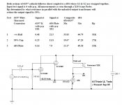
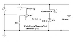
The trial circuit is quite simple, a 6F6 DC driven by the cathodes of parallel sections of a 6SN7GT. The anodes of the 6SN7GT could be alternatively connected to the B+ supply, the OPT CT or the plate connexion of the 6F6. That varies the amount of NFB applied to the anodes of the 6SN7GT. The resulting reach thru to the 6SN7GT cathode is (1/mu). I’ve put the test circuits & results into attachments.
I never did build the complete PP UL circuit. I realized that the driver plate(s) direct to B+ version was used commercially in some radios in the 30s. If you look at the base connexions on the octal 6N6G & 25N6G they are identical to many common power tubes such as the 6F6GT, 6K6GT, 6V6GT & so on. In the circuit they are self biasing, no cathode resistor required. But they did not catch on. Probably more expensive to build these tubes than the corresponding pentodes with there two cathodes, etc. An interesting exercise.
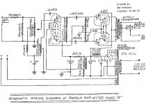
Here are links to a family of tubes suitable for an all triode PP UL amp.🙂 The Rockolab amp could easily be modified for UL. Or a similar amp with discrete triodes. So all triode UL is a project for the keeners on DIY.
http://frank.pocnet.net/sheets/049/6/6AC5GT.pdf
http://frank.pocnet.net/sheets/127/2/25AC5GT.pdf
http://frank.pocnet.net/sheets/127/6/6B5.pdf
http://frank.pocnet.net/sheets/084/6/6N6G.pdf
http://frank.pocnet.net/sheets/127/2/25B5.pdf
http://frank.pocnet.net/sheets/049/2/25N6G.pdf
Attachments
Thank you triode_al bhai for your interesting input. Then why we run after 3K primary for 300B why nor say 500 ohms (in SE)? Anybody else on the subject?
Regards
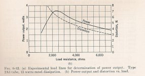
Theory shows max power for an ideal triode occurs at Rl = 2rp. For practical toobs that would be closer to Rl = 2rp. If the Rl is pushed lower D% increases rapidly. Applies to All Triodes, whether voltage or power amps. All well covered in something called a book!😀
Attachments
6.5k,7k, 8k is not a big deal. Exact OPT impedance depends on exact OP and exact output load. And there is no such thing as exact output load rather there is a range.
For me it is difficult to explain because one aspect relates to many others. Please consider that for now that 6.5k or 8k instead of 7k is okay. Please note data sheet OPT primary impedance comes from fixed resistor connected with secondary.
Regards
In the manufactures lab load impedance is applied across a suitable, low loss choke in the plate circuit. Powered by a regulated PS. The measurements are obtained using a wattmeter in order to avoid problems with stray impedance. The published spec is the result of large numbers of random samples.
Triodes can be loaded over a wide range, keeping in mind a lower limit on Rl.
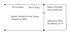
Pentodes are very particular. Since the load will probably be a loudspeaker, pick a steeper than recommended load (lower impedance). That will allow for the speakers impedance in its enclosure to go high at the ends of the spectrum as it often does. I use a speaker simulator network to test amplifier stability.😀
Attachments
Your understanding of the technical aspects is obviously much deeper than mine.
In the PP 6N6G I built, I did add some NFB. But I don't have a scope or any way to measure it. I just do it by ear and it did tighten up the bass a bit. It didn't actually sound too bad without any but bass guitar was more defined with a bit added.
Here's a thread on that build. It's just a modded Magnavox amp that came out of an old console stereo. It's ugly but sounds great.
Magnavox 175/185 Build . . . With a Twist | Audiokarma Home Audio Stereo Discussion Forums
If you were to apply a step function to the 6N6G amp driving that speaker, a scope attached to the speaker leads would shew a ring waveform that decays as an exponential. Easy to do with a single cell & a scope🙂
NFB would fix that. Or leave it & enjoy.
I'm not using any NFB with the 26 - 6N6G SET I have breadboarded. It sounds fine to me without it. I don't listen to much music that's bass heavy but when I tested it with a CD that has some pretty low and thumpy synth bass it was really solid.


- Home
- Amplifiers
- Tubes / Valves
- SE Amp with Thoriated Tungsten output tube