- MZM using 0R1/5W/WW
-who needs bleeder resistors? use brain instead ....... I'm bleeding my PSU simply staring at it .......... or mount some underneath; 2K2/1W will do the job .......... or just leave to amp to bleed its own PSU
-10-22R, small one, 10mm Dia
-who is gonna prevent you, in your own overachiever game? half of DIY fun is in that
-one Donut 400VA, connected to measly EU 230Vac; 400/230=1A74; 2AT rarely does the job (even with soft start it'll pop too often) but 2A5T will do; "T" means 'träge" in Austrian language
- R1, 2: cool, thanks!
- I tried with my brain but the electricity stayed... I'm not on the dark side of the force

- NTC: thanks!
- overachieving is is something I learned from your Mightiness

- 2,5AT: thanks for the confirmation, especially the lession in Austrian language


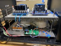
Some progress, but still lot to do 


Too lazy to search for that reference but why is it base plate lip up again?
I won't mention which way I have them installed in my amps 😗
I won't mention which way I have them installed in my amps 😗
Thankslookin' sissy
base plate lip up!!

Base plate... I have no wiring under the plate (also not in the M2x and The Source power supply, every wire "in the air", and have absolutely no hum), so I'll go that way

nice trafo , where came from ?
Hi ZM,
your PSU board has two soldering pins marked with "sense +" and "sense -"; what's the purpose?
Many thanks
your PSU board has two soldering pins marked with "sense +" and "sense -"; what's the purpose?
Many thanks

one day, if I decide to use R of CRC for Iq/biasing reference, in some future amp
2 tiny aux wires (one per rail), coming to amp board

2 tiny aux wires (one per rail), coming to amp board

Making some progress on Scryer.
Boards almost fully populated, heatsinks drilled/tapped for K2087 and THF-51(in case the little “used” Tokin goes kaput) and power supply output verified at +/-28.5VDC under 1.8A load.
Boards almost fully populated, heatsinks drilled/tapped for K2087 and THF-51(in case the little “used” Tokin goes kaput) and power supply output verified at +/-28.5VDC under 1.8A load.
Attachments
Really cool, I especially like your two-story buildingMaking some progress on Scryer.
Boards almost fully populated, heatsinks drilled/tapped for K2087 and THF-51(in case the little “used” Tokin goes kaput) and power supply output verified at +/-28.5VDC under 1.8A load.

🤣🤣
Nice one von Ah! Don’t forget to add “and storage” for the gear piling up😳
Yup, dual mono supply with SLB’s with 24vac trafo secondaries.
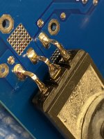
Ran into a small issue bending and soldering the legs of the K2087’s. Since the legs were added to the nubs left from being cut off the original use of these SIT’s, they are very delicate to form without falling off. After I got them into position and soldered to the pcb, I re-soldered the joints between the nubs and retrofit legs. Hopefully this will not break and cause major failure. I’m still not feeling confident in the reliability of these devices because of this. Thinking about aborting this mission and using the more robust THF-51’s??
Attachments
recipe from the past - you can always make solid core wire loop (shape of long U) , solder it (bottom of U) to transistor pin near the body and then solder end of loop in pcb pad
if you take a look at my shenanigans on T-Beds, you'll often see that I'm leaving mosfet pins untouched, making connection to pcb with short solid wire, exactly to avoid damage of mosfet pins so I can use them later for same purpose
reason - sometimes was needed to bend them upwards, sometimes downwards
of course, due to maltreatment, I had some mosfets with short pins, broken exactly where bend usually is, so salvage is easy that way - still perfect part
leftover pins of 3W MOX resistors, or 3A diodes or (best solution) simply - solid core wire of same Dia - perfect for the job
though, lately I'm making pcbs routing strictly in a way that mosfet (whatever) is sandwiched between hsink and pcb, so pins are always going upwards (same as you did show in last pic)
- Home
- Amplifiers
- Pass Labs
- Scryer ... or how F8 met Mighty SissySIT


