Gentlemen,
quite some discussions on this board deal with screen driven sweep tubes. I would like to draw your attention to my observation, that when screen-driving certain types which make use of beam forming plates for secondary electron emission suppression one rather obviously loses the benefits of said secondary electron emission suppression - at least this is my interpretation of the plots I made, please correct me if I am wrong.
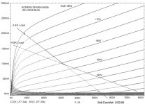
In datasheets or application notes, plots for screen drive of sweep tubes are not that commonly published. The 1st attachment shows a graph for a screen driven sweep tube from an application note.
Only few Spice models are available, but they give an extremely over-simplified view on reality; I suppose the curves from the 1st attachment were generated by such a model.
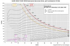
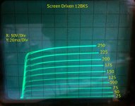
When measuring and plotting the same type of tube in real life using the same conditions (like prebiasing @ -33V Eg1) I get what you see in the 2nd attachment.
Now you can argue I didn´t connect the beam forming plates to the cathode with this certain sweep tube type, but I did. Just to make sure, I attached the plot of a sweep tube type which has an internal connection between the beam forming plates and the cathode, see 3rd attachment. Please note there is not only one massive kink, but also a much slighter additional kink (both marked red).
How do you interpret these graphs, what is your theory about the physical effects that (seemingly) cause the return of the evil tetrode kink when screendriving such sweep tube types? (Bonus points for giving an explanation of the much slighter 2nd kink).
What would be the consequences to consider when designing an amp with such screen driven sweep tubes? I mean, obviously it would be rather hard not to enter the instability / kink area at lowish Ea with real life reflected loads like real life speakers...
Regards, Tom
quite some discussions on this board deal with screen driven sweep tubes. I would like to draw your attention to my observation, that when screen-driving certain types which make use of beam forming plates for secondary electron emission suppression one rather obviously loses the benefits of said secondary electron emission suppression - at least this is my interpretation of the plots I made, please correct me if I am wrong.
In datasheets or application notes, plots for screen drive of sweep tubes are not that commonly published. The 1st attachment shows a graph for a screen driven sweep tube from an application note.
Only few Spice models are available, but they give an extremely over-simplified view on reality; I suppose the curves from the 1st attachment were generated by such a model.
When measuring and plotting the same type of tube in real life using the same conditions (like prebiasing @ -33V Eg1) I get what you see in the 2nd attachment.
Now you can argue I didn´t connect the beam forming plates to the cathode with this certain sweep tube type, but I did. Just to make sure, I attached the plot of a sweep tube type which has an internal connection between the beam forming plates and the cathode, see 3rd attachment. Please note there is not only one massive kink, but also a much slighter additional kink (both marked red).
How do you interpret these graphs, what is your theory about the physical effects that (seemingly) cause the return of the evil tetrode kink when screendriving such sweep tube types? (Bonus points for giving an explanation of the much slighter 2nd kink).
What would be the consequences to consider when designing an amp with such screen driven sweep tubes? I mean, obviously it would be rather hard not to enter the instability / kink area at lowish Ea with real life reflected loads like real life speakers...
Regards, Tom
Attachments
Hi Tom;
I believe the answer is in your experiment setup. I can't imagine negative resistance in triode.
I believe the answer is in your experiment setup. I can't imagine negative resistance in triode.
It is a triode with a rather positive grid so secondary emission complicates things. Do the kinks disappear if the beam plates/g3 are more negative?
It might also be interesting to see the g2 current - does it go negative at any point?
It might also be interesting to see the g2 current - does it go negative at any point?
Shown below are the results I got measuring a 6CD6GA in screen driven mode. These were static measurements taken a point at a time, rather than swept.
A source follower was used to drive the screen grid.The control grid was tied to cathode. I should probably try the tube in question at the beginning of this thread, as I have a few handging around.
A source follower was used to drive the screen grid.The control grid was tied to cathode. I should probably try the tube in question at the beginning of this thread, as I have a few handging around.
Attachments
Hi Wavebourn,
For the very slight kink, yes, that may be. For the large kink I don´t think so, since at least two people confirmed with their own measurements. When I showed these plots in a lecture at ETF06, some known experts there didn´t object, one of them showing a screen driven EL509 based design in his own lecture. I am sure your also can check yourself, if still in doubt. Just make sure to use appropiate PSUs when doing the measurements...
What do you think about Dynatron - Wikipedia, the free encyclopedia as a cause and explanation? As I understand it, it is about the same effect that causes what is called (translated) "Barkhausen oscillation" in German literature. Also, "Dynatron" seems to be known in Russian literature, but unfortunately I cannot read that language.
Regards, Tom
I believe the answer is in your experiment setup.
For the very slight kink, yes, that may be. For the large kink I don´t think so, since at least two people confirmed with their own measurements. When I showed these plots in a lecture at ETF06, some known experts there didn´t object, one of them showing a screen driven EL509 based design in his own lecture. I am sure your also can check yourself, if still in doubt. Just make sure to use appropiate PSUs when doing the measurements...
I can't imagine negative resistance in triode.
What do you think about Dynatron - Wikipedia, the free encyclopedia as a cause and explanation? As I understand it, it is about the same effect that causes what is called (translated) "Barkhausen oscillation" in German literature. Also, "Dynatron" seems to be known in Russian literature, but unfortunately I cannot read that language.
Regards, Tom
Hi DF96,
I didn´t check this but I dimly remember to have seen PL509 based TV sweep circuitry that runs the beam plates at negative voltage level referenced to cathode. Maybe -30V or something like that, but I am not sure. If so, that may be a hint that designers of such TV sweep circuits knew about how to suppress such instability area effects caused by secondary emission by lowering Ug3 below cathode level, indeed.
The pink curves in the EL509 plot show Ig2 at least over a small range where I expected something interesting to happen. In the kink valley area, you see Ig2 rise when Ia falls. Simplified, Ia + Ig2 = Ik still holds true within expectations, supposing Ig3 to be negligible. I didn´t measure Ig3, though.
For the other specimen EL36, there is no chance to change Ug3 from Uk, since the beam plates are connected to the cathode internally.
Regards, Tom
It is a triode with a rather positive grid so secondary emission complicates things. Do the kinks disappear if the beam plates/g3 are more negative?
I didn´t check this but I dimly remember to have seen PL509 based TV sweep circuitry that runs the beam plates at negative voltage level referenced to cathode. Maybe -30V or something like that, but I am not sure. If so, that may be a hint that designers of such TV sweep circuits knew about how to suppress such instability area effects caused by secondary emission by lowering Ug3 below cathode level, indeed.
It might also be interesting to see the g2 current - does it go negative at any point?
The pink curves in the EL509 plot show Ig2 at least over a small range where I expected something interesting to happen. In the kink valley area, you see Ig2 rise when Ia falls. Simplified, Ia + Ig2 = Ik still holds true within expectations, supposing Ig3 to be negligible. I didn´t measure Ig3, though.
For the other specimen EL36, there is no chance to change Ug3 from Uk, since the beam plates are connected to the cathode internally.
Regards, Tom
Hi wrenchone,
Extending your measurements with Ua below 100V down to, say, 10 or 20V would be most interesting, since the kink valley area with types EL509 and especially EL36 showed up below Ea=100V, unfortunately not covered by your plot. Also, prebiasing g1 with a constant voltage (as in my graphs) might make a difference. This g1 prebiasing is recommended in real world circuitry (using auto / cathode bias) to keep those fat sweep tubes from current runaway....
Same measuring method used with my plots. I don´t trust swept measurements for power tubes, because average Pa will be much less than when when running power tubes at, say, 80% Pa iddle in a real world amp circuit. Swept measurements just don´t show the real world thermic effects on internal electrode geometry, often causing a steeper gm close to the Pa,max hyperbole. Think "thermal runaway".
Regards, Tom
Shown below are the results I got measuring a 6CD6GA in screen driven mode.
Extending your measurements with Ua below 100V down to, say, 10 or 20V would be most interesting, since the kink valley area with types EL509 and especially EL36 showed up below Ea=100V, unfortunately not covered by your plot. Also, prebiasing g1 with a constant voltage (as in my graphs) might make a difference. This g1 prebiasing is recommended in real world circuitry (using auto / cathode bias) to keep those fat sweep tubes from current runaway....
These were static measurements taken a point at a time, rather than swept.
Same measuring method used with my plots. I don´t trust swept measurements for power tubes, because average Pa will be much less than when when running power tubes at, say, 80% Pa iddle in a real world amp circuit. Swept measurements just don´t show the real world thermic effects on internal electrode geometry, often causing a steeper gm close to the Pa,max hyperbole. Think "thermal runaway".
Regards, Tom
For normal tetrode/pentode operation to get more current you reduce the negative voltage on g1, while keeping g2 constant. The extra electron flow will establish (in a beam tetrode) a negative space charge near the anode - a virtual g3, but aided by beam plates.
For g2 drive, to get more current you increase g2 voltage. This means that at low anode voltages g2 is much more positive so is more likely to collect any secondary electrons, as well as more likely to intercept the primary electrons. The very positive g2 may also tend to eliminate the virtual g3 formed by a space charge near the anode. My guess is that you need to make g3 more negative so that anode secondaries are returned to the anode.
I'm not an expert on valve innards, so I could be wrong.
I ran the 6CD6GA curves originally to get enough data to establish the operating point for a screen drive SE amp, where it really doesn't make much sense to slam the positive drive when you can only take the negative excursion down to cutoff. Geroge Tubelab was able to yank the plates pretty much to ground in his P-P setup - in that case, the screens can act as surrogate plates and encounter a lot of abuse as a result. If I recall, he was actually able to melt some screen gids with that sort of treatment.
It would be interesting to take my 6CD6GA screen drive amp out of the living room and look at the plate excursion for varying levels of drive (something I've never done). Right now, the plate supply is at ~400VDC. The control grid is tied to the cathode through a 330 ohm resistor. I'm running fixed bias with the idle current set at around 65 mA. This is over the stated plate dissipation of the 6CD6, but the pair I'm using have held up nicely. I'm actually using a pair of CBS Hytron 6CD6Gs, as these have a beefier plate setup than the corresponding RCA units, which use a bizarre setup with paraleled elements. The Hytrons also have the old "coke bottle" envelopes, which impart a neat retro look to the amp. I've also run GE GA type bottles, as well as a pair of
Sylvania 6CB5As, all of which bias up satisfactorily in my circuit.
I was actually considering doing a higher power version of my 6CD6 amp using the 6P45S. It appeared to require some negative bias to tone down the screen grid sensitivity, but I never understood the necessity for the -33V used by others. I was thinking of starting with -8 to -10V. I suppose running a set of curves would be revealing.
To be honest, though, I think that the sweep tubes are kinda wasted in SE apps, as it's difficult to take advantage of the high peak cathode current capability in that application. The hungry filaments also make selecting appropriate power iron difficult - it's embarassing to be blowing more filament power than you're actually delivering to the speakers...
Howdy, All: since my next amp will be using sweep tubes (right now my pick is the 6CB5) and G2 drive is under consideration, though I'm only wanting 30-50W per channel, this thread caught my eye.
The post by Tom is interesting. I'm not here to try to give a theoretical explanation at the moment, that will come later, but I did pull up the 6KG6 curves as published by Amperex. The plate current curves for G2 at 160V do show a pronounce kink at G1 negative biases in the -30 region and even more at G2=175 so it follows that one might see some kinking at other voltages. It does not appear to be the classic tetrode kinking, though, which actually displays a negative resistance. Rather, it is a non linearity which I've seen in other tube curves, including the KT88. But one normally does not operate in those regions (meaning per published curves, not the highly biased G1 with G2 drive) so it may not be an issue. Perhaps the thing to do is to run with either 0 G1 or only a few volts negative for G2 drive.
BTW, snivets as the TV engineers called them, were controlled by bringing G3 positive with respect to the cathode by a few volts. Interesting! The reason why some of the latter sweep tubes separated the G3 connection (OK, beam forming plates) from the cathode.
Anyway, just my two cents worth, I'll be looking at other posts here with a lot of interest.
Rene
Gentlemen,
as it looks like so far by plots show not all screen driven sweep tubes tend to show such extreme kinks like types EL509 / 6KG6 / PL509 / 40KG6 or even mor, EL36 / 6CM5 / PL36 / 25E5.
I think more measurements would be needed to verify or falsify. Series of measurements with varying control grid prebias and even more interesting, with variation of the beam forming plates potential (if the tube under test allows for that) should give more insight.
I'll put the later (doing series of plots with variation of Eg3 voltage) on the to-do list, but please don´t hold your breath.
Thanks to all who contributed so far!
Regards, Tom
Please do look at the published curves for those tubes. The 6KG6 shows no "kinking" at all for its family of plate current curves vs G2 voltage when G1 is held at or close to zero, but shows large non linearities when G2 is held constant but G1 is taken way negative. You may not have any kind of an issue if you simply refigure your G2 drive load lines for G1 bias at or close to zero.
Even the venerable KT88 shows a LOT of plate current non linearities when G2 is held constant and G1 is taken way negative. But that combination, low plate voltage and very negative G1 is not the region where we operate these tubes.
You may not have any issues at all if you simply allow G1 voltage to be not quite so negative as you've been running.
Still, I'd love to see more measurements anyway, it's how we learn!
Good luck!
Rene
I also suspect the large negative g1 bias is the problem here causing the kinks. With a negative g1, the g1 wires cause a sheet beam focusing effect between grid1 wires, which is normally used (at fixed g2 volts) to avoid hitting the g2 wires (aligned grids effect normally for lowering g2 current). The sheet beam focal length changes with g2 volts and plate volts, and some combination will cause the electron sheets to defocus enough for them to hit the screen grid wires. The kinks are likely accompanied with peaks in g2 current. Putting g1 at cathode potential should eliminate the sheet focusing effects. Anything left would then likely be secondary emission effects.
It might also be possible to dynamically correct the g1 wire focusing (with a neg. bias on g1) if the g1 voltage is varied as some fraction of the g2 voltage. Then g2 current could be held to a minimum as intended (for the normal pentode mode). Perhaps something near 1/Mu of g2 versus g1. This approach has been tried before (on a curve tracer) with interesting results, since it can cut the required voltage swing of g2 in half for the same plate output (if the two grids can be adding, but would double the required g2 swing if they have to oppose each other for focusing, which seems more likely here).
It might also be possible to dynamically correct the g1 wire focusing (with a neg. bias on g1) if the g1 voltage is varied as some fraction of the g2 voltage. Then g2 current could be held to a minimum as intended (for the normal pentode mode). Perhaps something near 1/Mu of g2 versus g1. This approach has been tried before (on a curve tracer) with interesting results, since it can cut the required voltage swing of g2 in half for the same plate output (if the two grids can be adding, but would double the required g2 swing if they have to oppose each other for focusing, which seems more likely here).
Last edited:
Hi smoking-amp,
interesting explanation! Unfortunately it wouldn´t be wise to omit the (automatic, cathode) prebiasing in real world amps to circumvent what you think is the cause of the kinking.
Mr. Danielak (EL509 Svetlana app report) and Mr. Paravincini (EAR) used the auto prebiasing to keep these fat sweep tubes from thermal runaway, both used about Eg1= -33V, that´s why I used this also for the EL509 plot shown above. If prebiasing really is the cause of the kink, the (computed) "plot" from the Svetlana app report shown above is far from reality.
Screen drive plots from datasheets usually don´t use any control grid biasing (g1 simply strapped to cathode), indeed.
Regards Tom
It's hard to see from the published data that runaway is a big monster here. With a mild G1 bias, something in the -5 to -15 range, the idle condition is some G2 voltage value which would be quite low, producing very low plate current. Some people have used idle currents in the only very few milliamps range. I suppose one could still use a combination of fixed plus cathode self bias. My point is, at least at first glance, I don't see that G2 drive is necessarily a breeding ground for runaway conditions. IMHO, go less negative on the G1 bias, limit your desired power by restricting the swing at G2 with the added benefit of making it easier to design your driver and go for it.
Enjoy!
Rene
Enjoy!
Rene
Seeing as how these screen drive amps are usually run near class B, I would think that the usual automatic bias schemes would not work very well, causing tube cutoff after a loud signal passage. What you need for biasing is one of those fancy minimum current sensing (for class B) Op. Amp bias controllers for each tube. (minimum peak detector into an RCRC filter to act as a sample/hold, then compared with an adjustable Vbias reference level, then Vg1 bias gets applied ) Then you only need a small current sensing resistor in the cathode circuit for each tube.
Last edited:
Tom, does your setup employ G2 current limiting?
Keep in mind that in any pentode and especially BPT the screen grid current rises dramatically when the plate voltage gets near the screen grid voltage (what 'near' means is a function of the utbe geometry, for sweep tubes the plate has to get well below screen grid voltage for this to happen). Could that be the problem? Also, if it is, you might be getting combinations of voltages and currents that match the conditions at multiple places. Also, DF96 has a good point re beam plate voltage. Unfortunately not all tubes have a separate beam plate connection 🙁
Are you measuring plate or cathode current? I have a Tek curve tracer but it's basically designed for semiconductors although it goes up to well over 1kV. Measuring pentodes is a problem as I can only employ pulse measurements because it always starts the curve tracing from what would be Vak=0, at which point a dangerously high current is passing through G2...
Hi ilimzn,
Yes, the regulated PSU used for g2 feed is limited to 200 mA.
I am measuring directly at all electrodes. F.e, Ia is measured at the anode and Ig2 is measured at the screen grid, indeed.
Regards, Tom Schlangen
Tom, does your setup employ G2 current limiting?
Yes, the regulated PSU used for g2 feed is limited to 200 mA.
Are you measuring plate or cathode current?
I am measuring directly at all electrodes. F.e, Ia is measured at the anode and Ig2 is measured at the screen grid, indeed.
Regards, Tom Schlangen
- Status
- Not open for further replies.
- Home
- Amplifiers
- Tubes / Valves
- Screen driven sweep tubes - the return of the evil kink?